Low power LSSD flip flops and a flushable single clock splitter for flip flops

a flip flop and flip flop technology, applied in the field of low power lssd flip flops and a flushable single clock splitter for flip flops, can solve the problems of certain problems associated with dff apparatuses

Inactive Publication Date: 2001-10-16
IBM CORP
View PDF10 Cites 40 Cited by
  • Summary
  • Abstract
  • Description
  • Claims
  • Application Information

AI Technical Summary

Problems solved by technology

Unfortunately, there are certain prob...

Method used


Image

  • Low power LSSD flip flops and a flushable single clock splitter for flip flops
  • Low power LSSD flip flops and a flushable single clock splitter for flip flops
  • Low power LSSD flip flops and a flushable single clock splitter for flip flops

Examples


Embodiment Construction

As discussed above, the preferred embodiments of the present invention relate to flip flop apparatuses. A more complete discussion of the problems associated with these flip flop apparatuses follows in the Overview section. Because of the particular problems associated with these apparatuses, the Overview section is important in order to best understand the benefits and advantages of the present invention, as well as how the present invention solves these problems.

1. Overview

Returning to FIGS. 8, 9 and 10, during normal operation the Level Sensitive Scan Design (LSSD) A, B and C clocks are held at particular logic values (low, high and high logic values, respectively). When operated using the Edge (E) clock input, the apparatuses of FIGS. 9 and 10 consume more power than does the apparatus of FIG. 8.

Any transition of the E clock input, in FIGS. 9 and 10, causes a transition at the output of each of the four gates in the clock splitter 940. Furthermore, if one clock splitter 940 is s...


PUM


Abstract

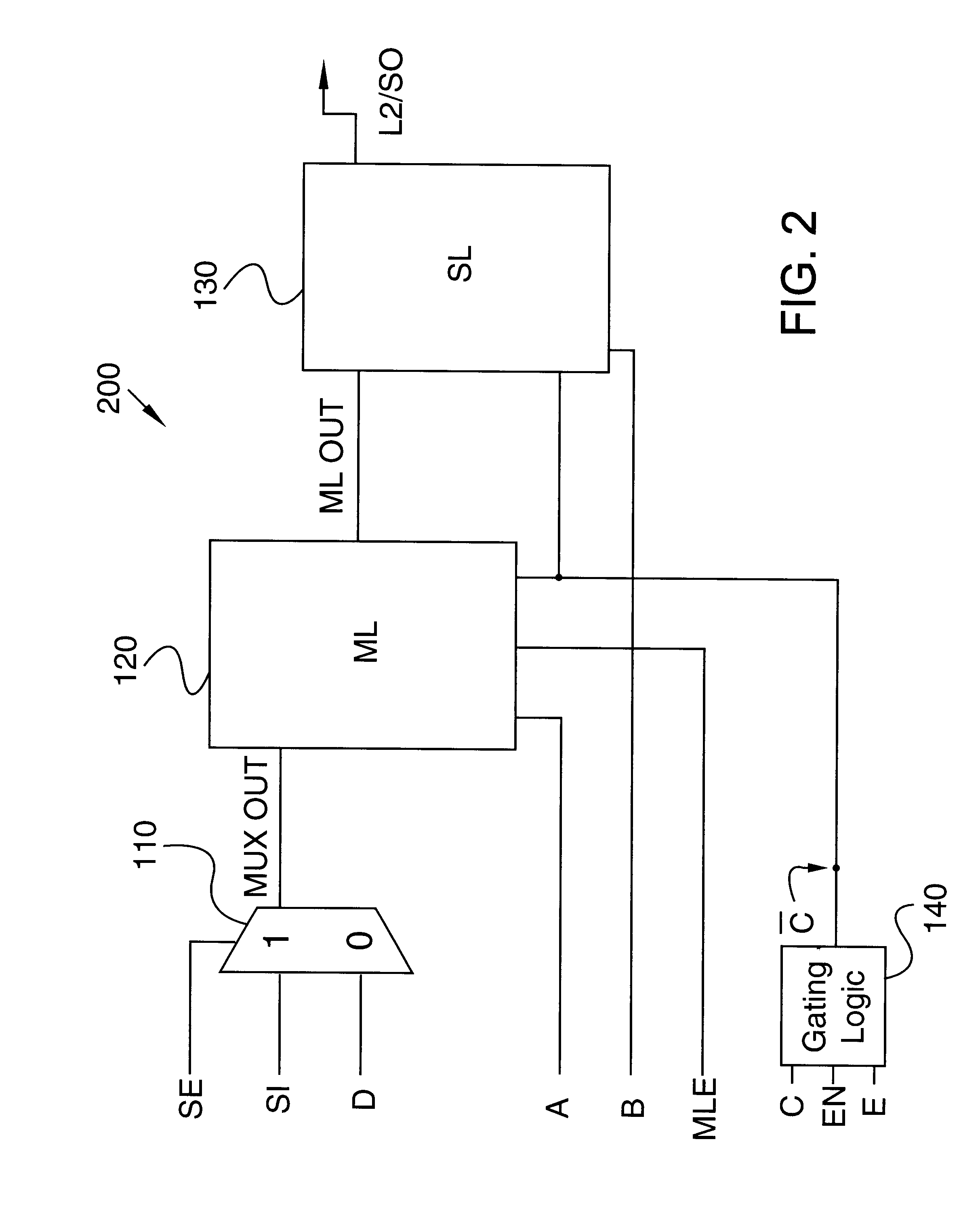
This invention reduces power in flip flop apparatuses by providing flip flop apparatuses that have fewer clock trees than prior art flip flops yet still support some or all of the Level Sensitive Scan Design (LSSD) functionality. In preferred embodiments of the present invention, one clock tree is used instead of two to provide lower power, and less switching devices in clocks splitters are used, which also provides lower power. Additionally, a flushable single clock splitter is provided that allows one clock tree to be used up to the flushable single clock splitter and provides two clocks on the output of the flushable single clock splitter. This saves some power yet still allows for dual clock flip flop designs.

Description

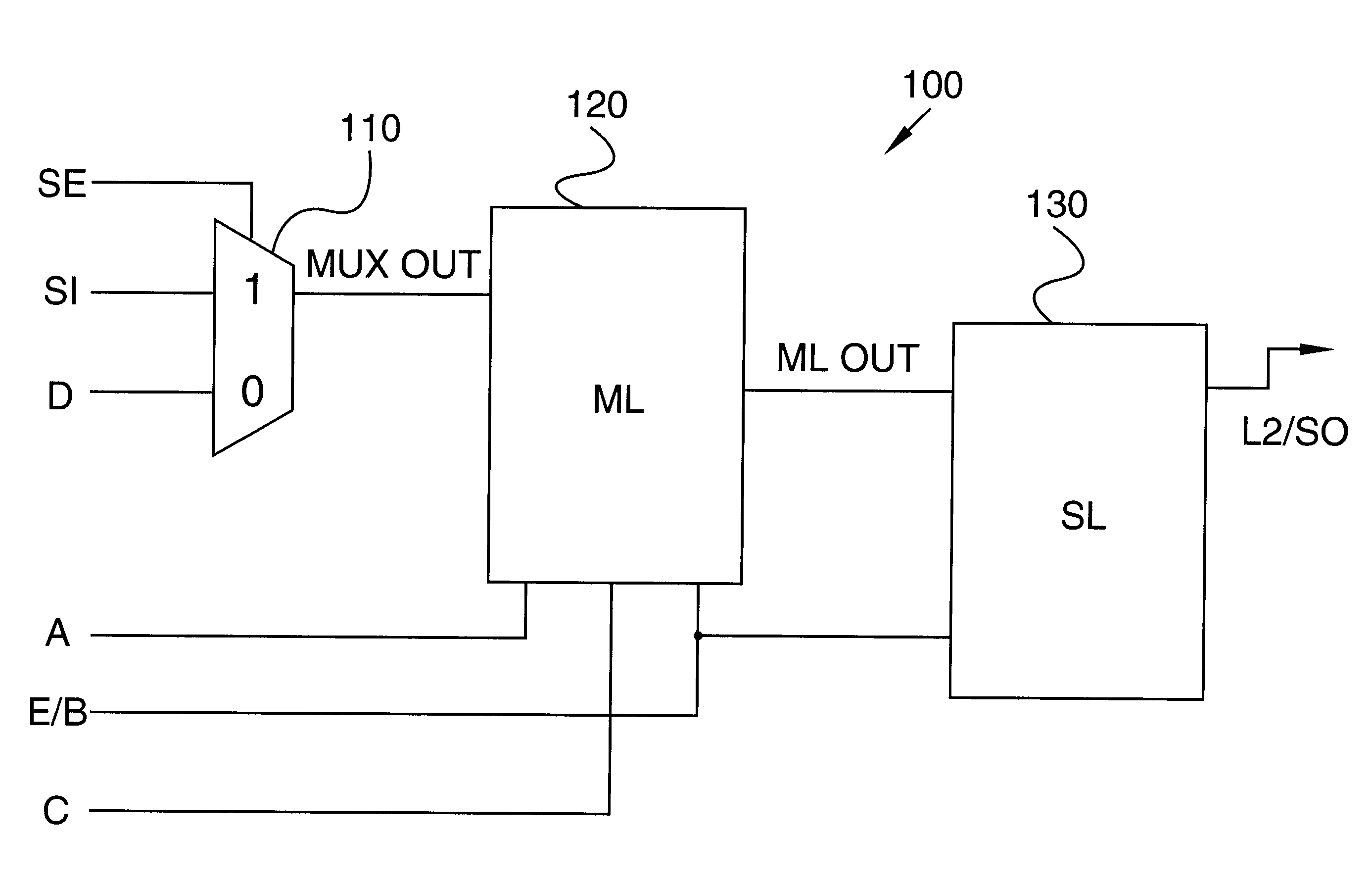
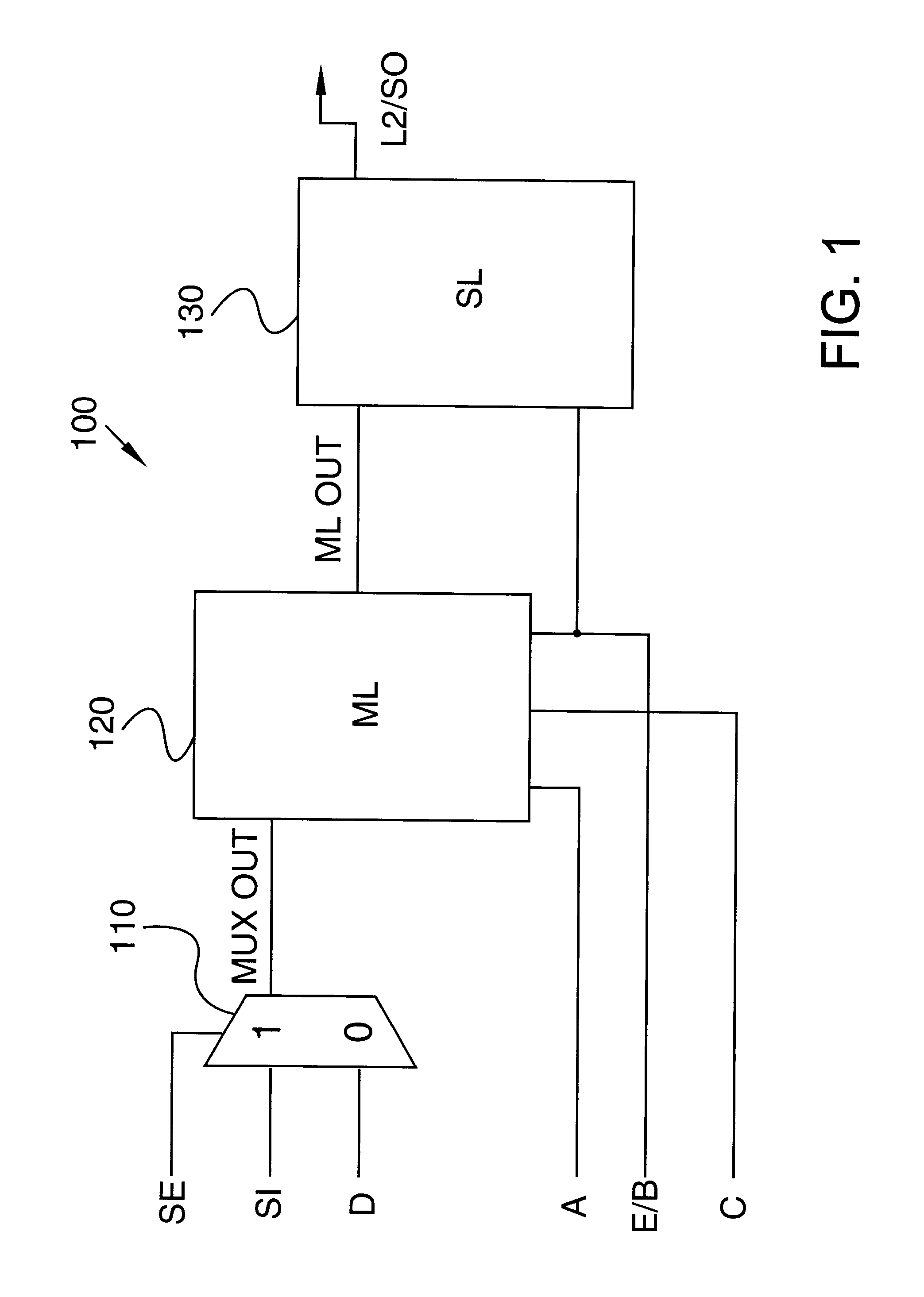
1. Technical FieldThis invention generally relates to Level Sensitive Scan Design (LSSD) circuits, and more specifically relates to low power LSSD flip flops and a flushable single clock splitter for flip flops.2. Background ArtFlip Flops are common devices that are used to allow data to be latched and propagated. A common type of D Flip Flop (DFF) apparatus is shown in FIG. 8. DFF apparatus 600 comprises a multiplexor (MUX) 610 having outputs 611, a Master Latch (ML) 620 having outputs 613 and 614, and a Slave Latch (SL) 630 having a Scan Out (SO) output. The ML is often referred to as latch "L1" and the SL is often referred to as latch "L2". DFF apparatus 600 also comprises a Scan In (SI) input, a Scan Enable (SE) input, a Data (D) input, and an Edge (E) clock input. The MUX 610 has an inverter I1 and two drivers D1 and D2. The ML 620 has inverters I7, I2, I3, and I8, and transistors T1 and T2. The SL 630 has inverters I4, I5, and I6 and has transistors T5, T6, and T7. The SE sign...

Claims


Application Information

Patent Timeline
IPC IPC(8): H03K3/037H03K3/00
CPCH03K3/0372H03K3/0375
Inventor GREGOR, ROGER P.OAKLAND, STEVEN F.SAITOH, TOSHIHARUVENTRONE, SEBASTIAN T.
Owner IBM CORP
Why Eureka
Try Eureka