Method for balancing a clock tree
a clock tree and clock signal technology, applied in the direction of generating/distributing signals, instruments, computing, etc., can solve the problems of not being as tightly grouped, practical for a designer, and the single clock signal driver normally cannot directly supply a clock signal to all such syncs
- Summary
- Abstract
- Description
- Claims
- Application Information
AI Technical Summary
Problems solved by technology
Method used
Image
Examples
Embodiment Construction
)
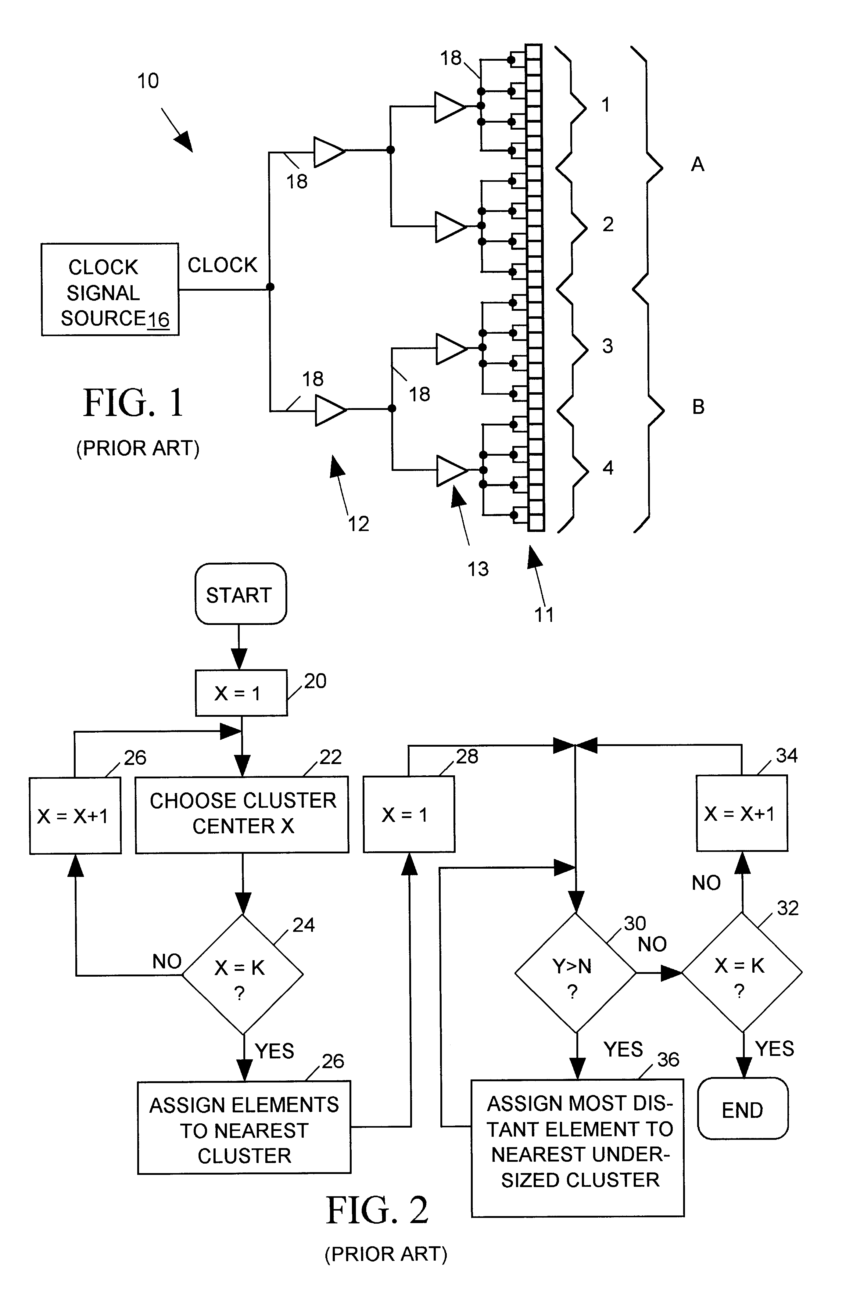
FIG. 1 is a block diagram of a typical prior art "clock tree" 10 implemented in an integrated circuit (IC) to provide a common clock signal (CLOCK) input to a number of circuit devices ("syncs") 11 such as flip-flops or latches. For simplicity FIG. 1 shows only 32 such syncs 11 but a large digital integrated circuit may have many thousands of such syncs. Since a single clock signal source 16 normally cannot drive a large number of syncs, clock tree 10 includes an array of buffers 12, 13 fanning out the CLOCK signal to spread the load over many buffers. In this simple example, two first stage buffers 12 fan the CLOCK signal out to four second stage buffers 13 which in turn fan the CLOCK signal out to the 32 syncs 11. The number of buffer stages, the number of buffers per stage and the number of buffers or syncs each buffer drives are matters of design choice that depend on such factors as the load capacity of the buffers forming clock tree 10, input impedance ...
PUM
 Abstract
Description
Claims
Application Information
 - R&D
- Intellectual Property
- Life Sciences
- Materials
- Tech Scout
- Unparalleled Data Quality
- Higher Quality Content
- 60% Fewer Hallucinations
Browse by: Latest US Patents, China's latest patents, Technical Efficacy Thesaurus, Application Domain, Technology Topic, Popular Technical Reports.
© 2025 PatSnap. All rights reserved.Legal|Privacy policy|Modern Slavery Act Transparency Statement|Sitemap|About US| Contact US: help@patsnap.com


