Clock gating of sub-circuits within a processor execution unit responsive to instruction latency counter within processor issue circuit

a technology of instruction latency counter and processor, applied in the direction of generating/distributing signals, instruments, computation using denominational number representation, etc., can solve the problem of increasing power consumption of such circuits

Inactive Publication Date: 2005-11-29
AVAGO TECH WIRELESS IP SINGAPORE PTE
View PDF17 Cites 22 Cited by
  • Summary
  • Abstract
  • Description
  • Claims
  • Application Information

AI Technical Summary

Problems solved by technology

As the frequencies increase (and the number of transistors on a chip also increases), the power consumption of such circuits increases.

Method used


Image

  • Clock gating of sub-circuits within a processor execution unit responsive to instruction latency counter within processor issue circuit
  • Clock gating of sub-circuits within a processor execution unit responsive to instruction latency counter within processor issue circuit
  • Clock gating of sub-circuits within a processor execution unit responsive to instruction latency counter within processor issue circuit

Examples


Embodiment Construction

Processor Overview

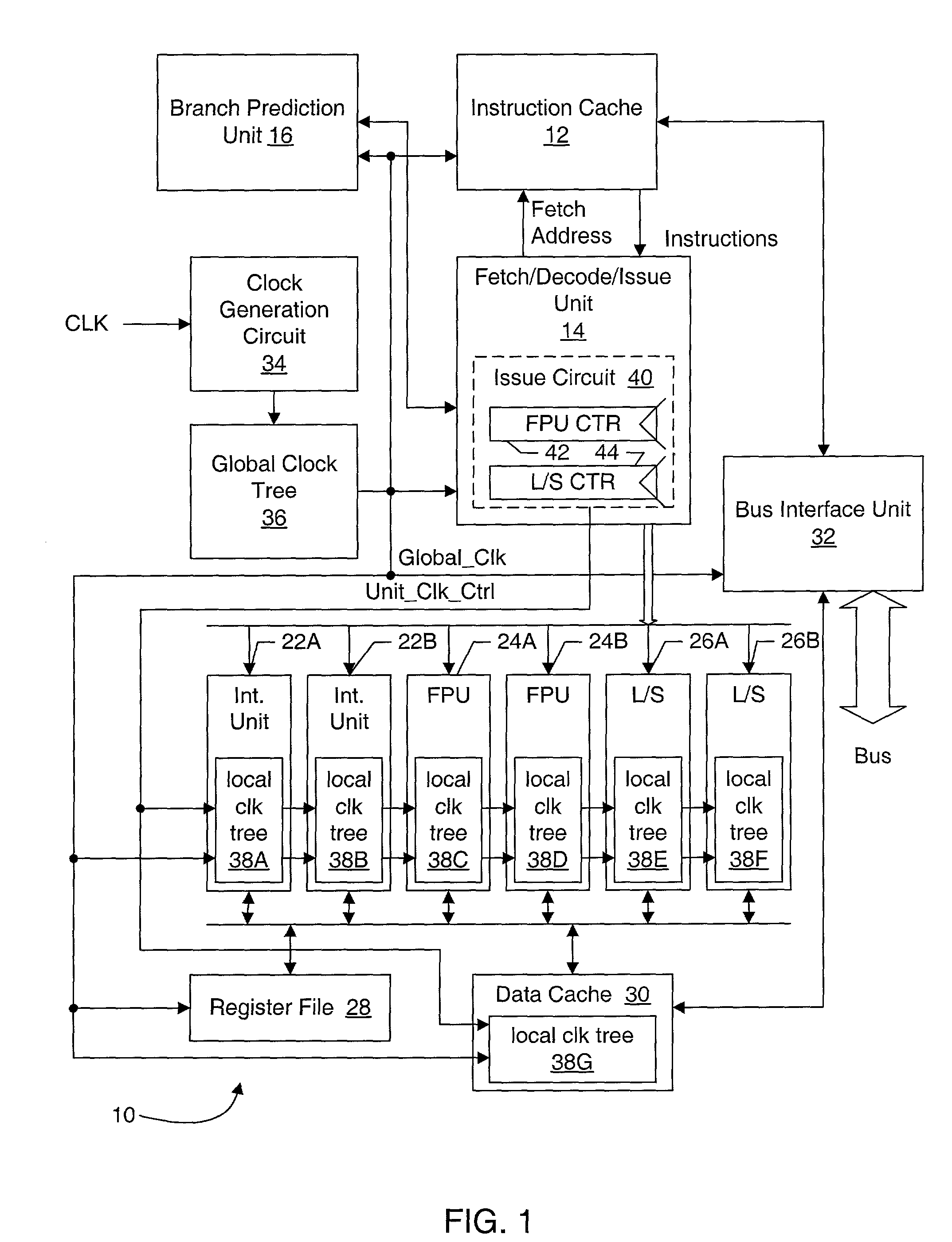
[0019]Turning now to FIG. 1, a block diagram of one embodiment of a processor 10 is shown. Other embodiments are possible and contemplated. In the embodiment of FIG. 1, the processor 10 includes an instruction cache 12, a fetch / decode / issue unit 14, a branch prediction unit 16, a set of integer execution units 22A–22B, a set of floating point execution units 24A–24B, a set of load / store execution units 26A–26B, a register file 28, a data cache 30, a bus interface unit 32, a clock generation circuit 34, and a global clock tree 36. The instruction cache 12 is coupled to the bus interface unit 32, and is coupled to receive a fetch address from, and provide corresponding instructions to, the fetch / decode / issue unit 14. The fetch / decode / issue unit 14 is further coupled to the branch prediction unit 16 and the execution units 22A–22B, 24A–24B, and 26A–26B. Specifically, the fetch / decode / issue unit 14 is coupled to provide a branch address to the branch prediction unit 16...


PUM


Abstract

A processor may include an execution circuit, an issue circuit coupled to the execution circuit, and a clock tree for clocking circuitry in the processor. The issue circuit issues an instruction to the execution circuit, and generates a control signal responsive to whether or not the instruction is issued to the execution circuit. The execution circuit includes at least a first subcircuit and a second subcircuit. A portion of the clock tree supplies a plurality of clocks to the execution circuit, including at least a first clock clocking the first subcircuit and at least a second clock clocking the second subcircuit. The portion of the clock tree is coupled to receive the control signal for collectively conditionally gating the plurality of clock, and is also configured to individually conditionally gate at least some of the plurality of clocks responsive to activity in the respective subcircuits of the execution circuit. A system on a chip may include several processors, and one or more of the processors may be conditionally clocked at the processor level.

Description

BACKGROUND OF THE INVENTION[0001]1. Field of the Invention[0002]This invention is related to the field of clocking of integrated circuits and, more particularly, to clock gating in integrated circuits.[0003]2. Description of the Related Art[0004]Digital circuits, including processors, systems-on-a-chip (SOCs), etc., are being designed to be operated at ever increasing frequencies. As the frequencies increase (and the number of transistors on a chip also increases), the power consumption of such circuits increases.[0005]One attempt to manage power in integrated circuits includes clock gating. Generally, at a single, predefined level of abstraction in the integrated circuit, the clocks may be selectively gated based on whether or not corresponding circuitry is in use. By deactivating the clocks, the corresponding digital circuitry may be prevented from switching and thus from consuming dynamic power.SUMMARY OF THE INVENTION[0006]A processor may include an execution circuit configured ...

Claims


Application Information

Patent Timeline
Patent Type & Authority Patents(United States)
IPC IPC(8): G06F1/08G06F1/10
CPCG06F1/08G06F1/10
Inventor SANTHANAM, SRIBALANVON KAENEL, VINCENT R.KRUCKEMYER, DAVID A.
Owner AVAGO TECH WIRELESS IP SINGAPORE PTE
Why Eureka
Try Eureka