Finger supporting structure

a technology of supporting structure and finger, which is applied in the field of finger supporting structure, can solve the problems that features cannot perform any role in generating the above-described resultant force of digits, and achieve the effects of enhancing the power, stability, accuracy, and efficiency of gripping action, and maximizing the resultant force of flexors and adductors of digits

Inactive Publication Date: 2001-10-23
CHO MYONG HO
View PDF18 Cites 72 Cited by
  • Summary
  • Abstract
  • Description
  • Claims
  • Application Information

AI Technical Summary

Benefits of technology

Thus, it is an object of the present invention to provide a finger supporting structure having finger supporting means to the bar-shaped handle of an implement, which can maximize the resultant force of the

Problems solved by technology

Thus, these features can not perform any role in genera

Method used


Image

  • Finger supporting structure
  • Finger supporting structure
  • Finger supporting structure

Examples


Embodiment Construction

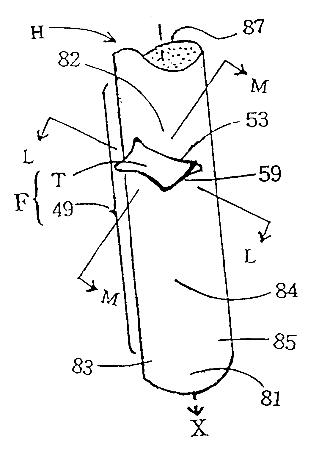
The finger supporting structure F of the present invention is comprised of an elongated bar-shaped grip portion having adequate length and thickness for a hand to grasp and a finger supporting means integrally formed thereto.

For convenience, the term "finger supporter" is used to designate said finger supporting means.

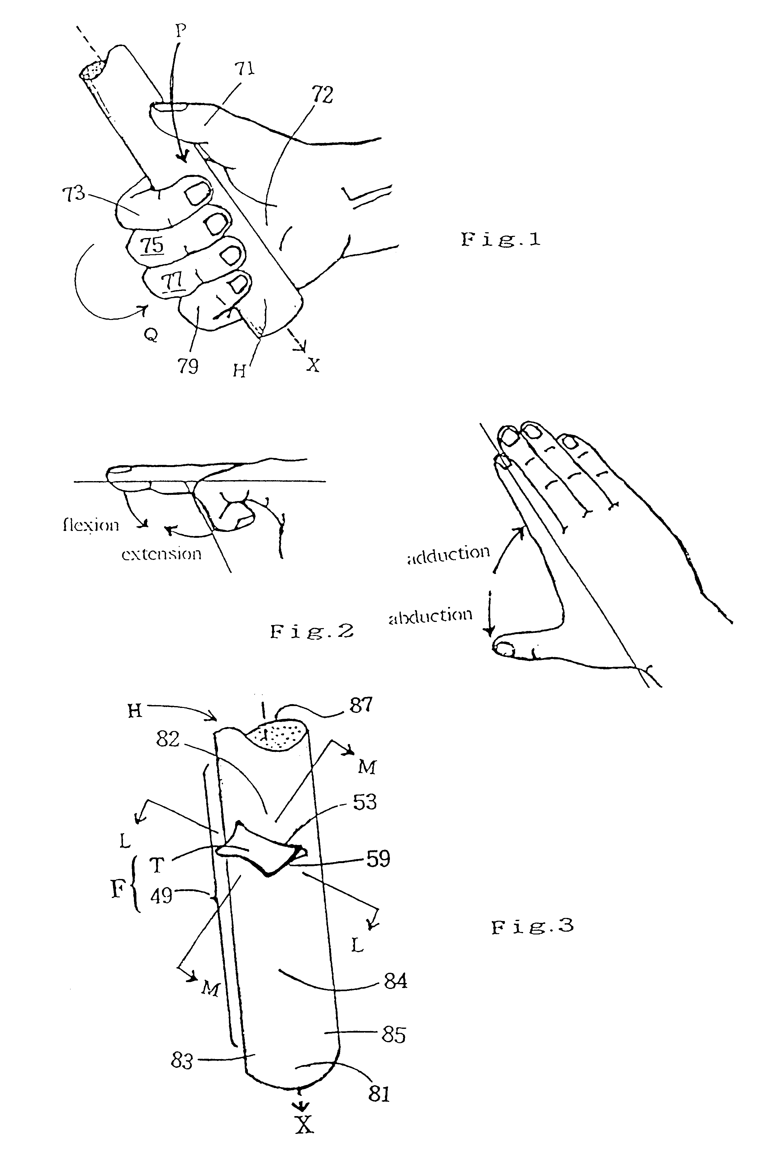
In FIG. 3, a finger supporting structure F comprised of a grip portion 49 and a finger supporter T integrally formed thereon as a unified body is embodied in the gripping part H of an implement.

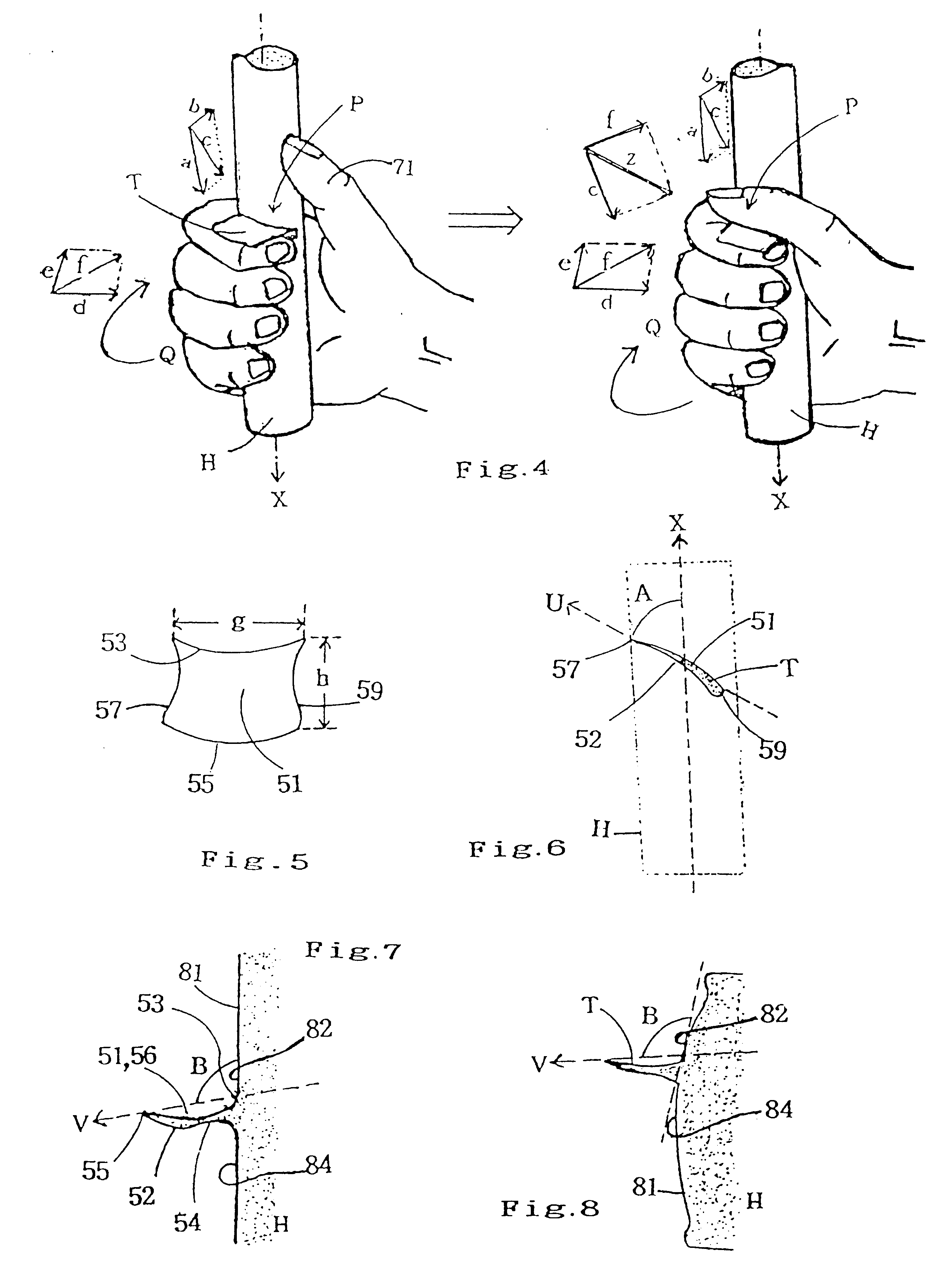
FIG. 4 illustrates the procedure that a hand grasps the gripping part H of an implement in FIG. 3.

As shown in FIG. 4, first, as the drawing force of the flexors of the thumb (vector "a") is supported by the finger supporter T and the drawing force of the adductors of the thumb (vector "b") is supported by the grip portion 49, maximum resultant force "c" of the thumb can be exerted to the optimal, and

second, as the drawing force of the flexors of the four fingers (vector "d") is ...


PUM


Abstract

A finger supporting structure (F) includes a grip portion and a finger supporter (T) formed thereto. The grip portion is of an elongated bar shape and has adequate length and thickness for a hand to grasp. The grip portion is either all or part of a grasping member of an implement or all or part of a gripping member (G) having internal hole to receive the grasping member of an implement. The finger supporter (T) is a laterally extending projection rigidly formed, in one piece, on the grip portion. The finger supporter (T) is angled to be inclined with respect to the axis (X) of the grip portion in order that the resultant force of the muscles of the digits and hand can be generated and exerted to the optimal. The finger supporting structure (F) is embodied in the grasping members of various implements and thereby provides gripping parts (H) having finger supporter (T) of the implements.

Description

The present invention relates to a finger supporting structure comprised of an elongated bar-shaped grip portion having adequate length and thickness for a hand to grasp and a finger supporting means rigidly formed on said grip portion in one piece.Since the invention of tools, there have been numerous implements, equipments, instruments, devices, tackles, appliances, facilities, articles, and so on, each of which has a bar-shaped handle or gripping part which are intended to be grasped and moved by the hand so as to effect some results.For convenience, throughout the specification, the term "implement" is used to representatively designate these tools, and so on, each of which has a bar-shaped gripping part for the users to grasp.The description and drawings related to the grip portion 49 or gripping member G having finger supporter T of the present invention are intended mostly for the right hand, it being understood that that for the left hand can be made as a mirror-image versio...

Claims


Application Information

Patent Timeline
IPC IPC(8): A63B59/00B25G1/00B25G1/10
CPCA63B21/1469A63B59/0014B25G1/102A63B5/20Y10T16/498A63B21/0726A63B29/08A63B59/0025A63B59/0029A63B59/0051A63B59/02A63B59/06A63B2208/12Y10S16/12Y10T16/476A63B21/0724A63B21/4035A63B60/12A63B60/10A63B60/32A63B59/20A63B60/08A63B60/14A63B2102/18A63B59/50A63B53/14A63B49/08A63B60/06
Inventor CHO, MYONG HO
Owner CHO MYONG HO
Why Eureka
Try Eureka