Fuel tank and fuel feeding apparatus used therefor

a technology of fuel tank and fuel feeding apparatus, which is applied in the direction of tank vehicles, transportation and packaging, transportation items, etc., can solve the problems of poor workability and achieve the effect of facilitating the attachment of inlet filler pipes

Inactive Publication Date: 2001-10-23
TOYODA GOSEI CO LTD
View PDF11 Cites 40 Cited by
  • Summary
  • Abstract
  • Description
  • Claims
  • Application Information

AI Technical Summary

Benefits of technology

is to provide a fuel feeding mechanism that facilitates attachment of an inlet filler pipe through which a supply of fuel is fed into a fuel tank.
In accordance with still another embodiment of the fuel tank, the casing includes a first casing section and a second casing section, which are separate elements but are capable of being integrated with each other. The valve attachment is disposed on the first casing section and the valve disc is disposed on the second casing section. In the case where the shape of the valve disc is varied according to the shape of the tank main body, this arrangement does not require a variation in total structure of the check valve, but only a variation in shape of the second casing section with the valve disc. This does not require a new mold for the whole check valve, and thus, simplifies the manufacturing process.

Problems solved by technology

The prior art technique carries out the attachment work of the fuel feeding mechanism FS at the bottom of the vehicle, and thereby has poor workability.

Method used


Image

  • Fuel tank and fuel feeding apparatus used therefor
  • Fuel tank and fuel feeding apparatus used therefor
  • Fuel tank and fuel feeding apparatus used therefor

Examples


first embodiment

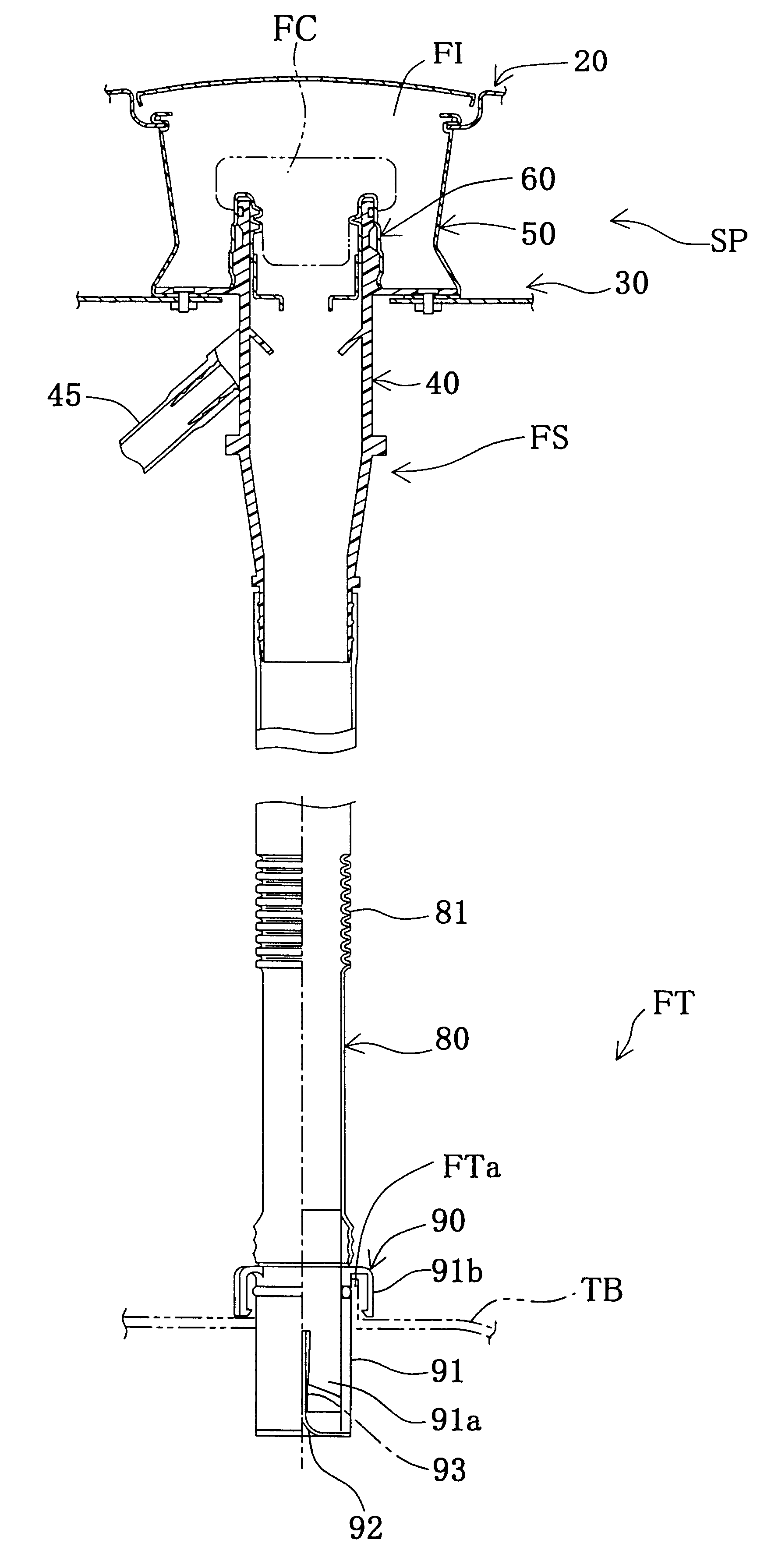
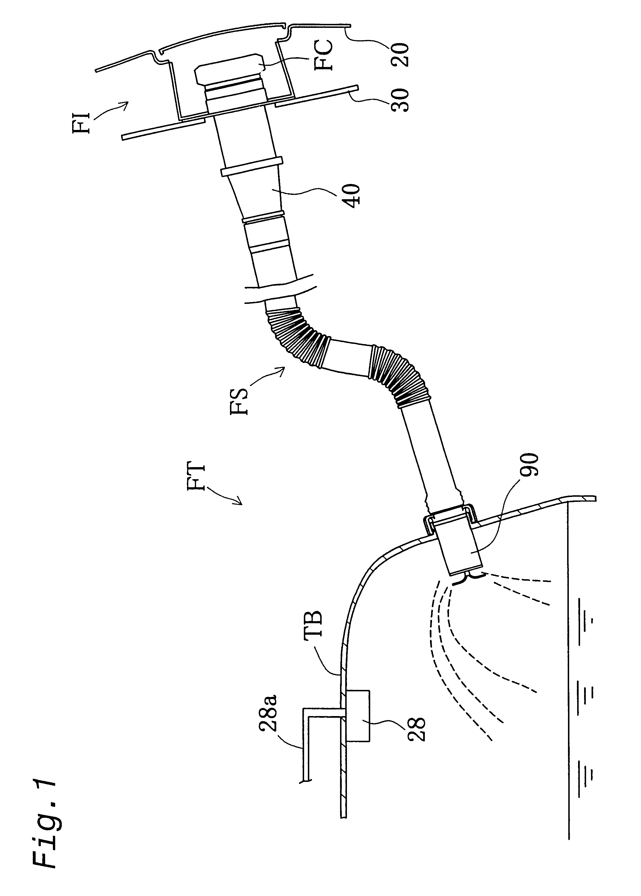
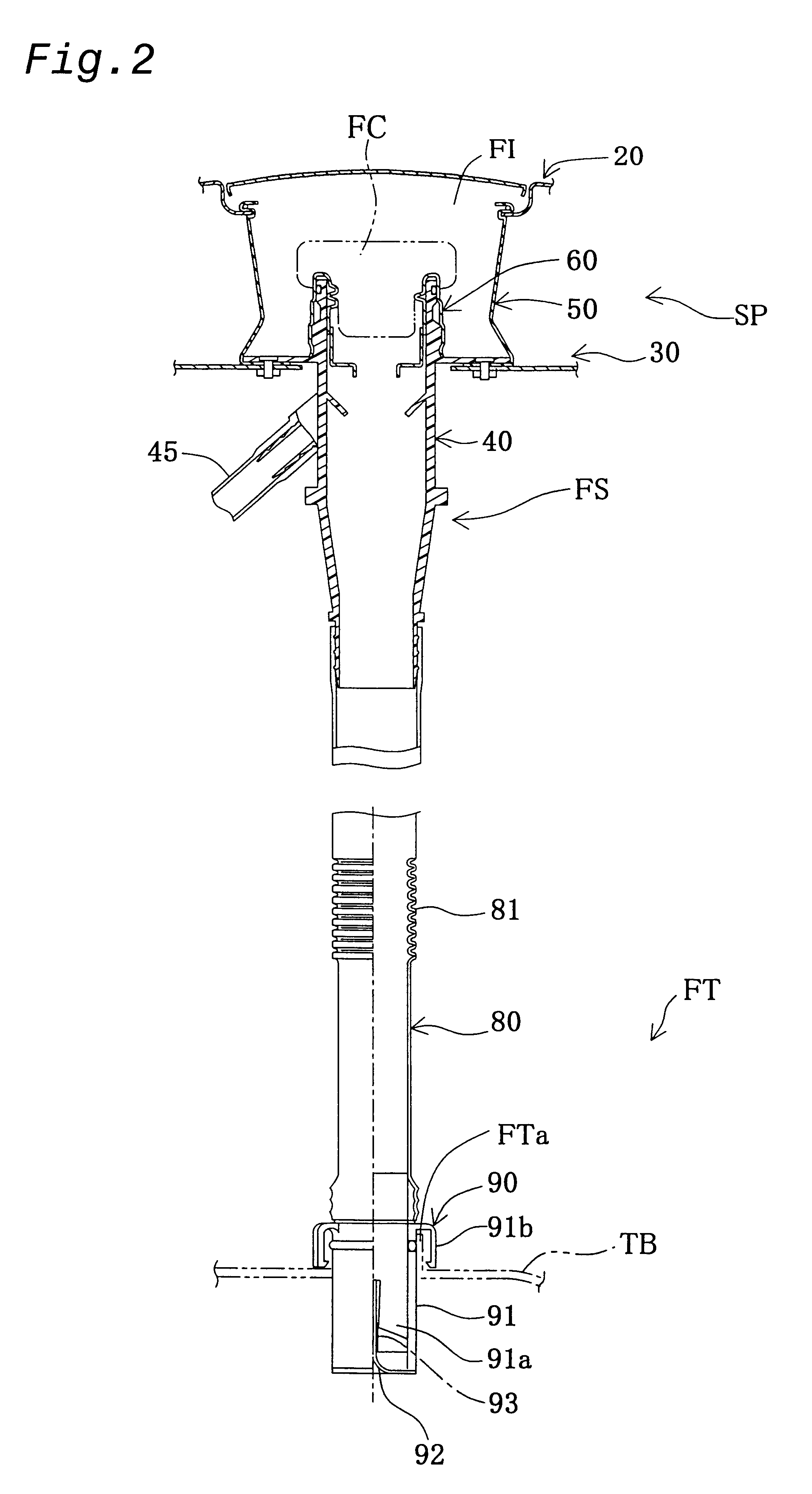
FIG. 2 is a partly broken sectional view illustrating the fuel feeding mechanism FS for feeding a supply of fuel to the tank main body TB of the automobile in a first embodiment according to the present invention. The fuel feeding mechanism FS connects a fuel inlet unit FI, which is attached to an outer side member 20 (a constituent of an outside plate of the vehicle) and an outer wheel house 30 (a member on the vehicle body), with the tank main body TB. The fuel feeding mechanism FS includes a filler cap FC, an inlet filler pipe 40, a seal cup 50, a connector 60, a connection pipe 80, and a check valve 90. A space SP between the outer side member 20 and the outer wheel house 30, that is, a part of the outer wheel house 30 in the vicinity of the filler cap FC, is sealed with the seal cup 50.

When the user opens the filler cap FC and feeds a supply of fuel from a filler gun (not shown) into the inlet filler pipe 40, the supply of fuel flows through the inlet filler pipe 40 and the con...

third embodiment

Like the protector 85 of the third embodiment discussed above, the protector 150 of the modified structure facilitates the attachment of fuel feeding mechanism FS to the vehicle. A connection pipe 80 having the bellows 81 at the place of mounting the protector 150 enables the curved shape of the connection pipe 80 to be kept more readily, as shown in FIG. 39D.

In addition to the above modified structure, other modifications, changes, and alterations are also possible without departing from the scope or spirit of the main characteristics of the present invention. Some examples of such modification are discussed below.

In the third embodiment discussed above, the protector 85 is equally parted into the upper half section 86 and the lower half section 87. The protector may, however, be divided into upper and lower sections at any ratio in the range of 2 / 3 to 1 / 3. The protector divided into the upper and lower sections at the ratio of 2 / 3 desirably has improved shape-keeping properties wh...


PUM


Abstract

A fuel feeding mechanism of the present invention has an inlet filler pipe that runs from a filler opening formed in an outer side member of an automobile to a fuel tank. The inlet filler pipe has a flange. The inlet filler pipe is attached to an outer wheel house across a seal cup that is held between the flange of the inlet filler pipe and the outer wheel house. The inlet filler pipe is inserted from outside of the automobile through the filler opening toward the fuel tank and is attached to the outer wheel house. This arrangement enhances workability.

Description

1. Field of the InventionThe present invention relates to a fuel feeding mechanism that connects a filler opening formed in an outside plate of a vehicle with a fuel tank and leads a supply of fuel to the fuel tank.2. Description of Related ArtFIG. 41 shows a prior art fuel feeding mechanism FS for feeding a supply of fuel into a fuel tank of an automobile (not shown). The fuel feeding mechanism FS connects a fuel inlet unit attached to an outer side member 210, which is a constituent of an outside plate of a vehicle, to the fuel tank. The fuel feeding mechanism FS includes an inlet filler pipe 220 attached to the end of the fuel inlet unit and a hose (not shown) connecting with the inlet filler pipe 220. While a filler cap FC is removed, a supply of fuel is fed from a filler gun (not shown) into the inlet filler pipe 220. One end of the inlet filler pipe 220 is attached to the outer wheel house 230, which faces the outer side member 210 across a predetermined space. An electric sys...

Claims


Application Information

Patent Timeline
Patent Type & Authority Patents(United States)
IPC IPC(8): B60K15/04
CPCB60K15/04B60K2015/03401Y10T137/6881Y10T137/86324Y10T137/86332Y10T137/86372
Inventor GOTO, HISATSUGUHORI, TOMOKAZUAOKI, TOMOHIDE
Owner TOYODA GOSEI CO LTD
Why Eureka
Try Eureka