Diaphragm pump and a receptacle fitted therewith

a diaphragm pump and receptacle technology, which is applied in the direction of piston pumps, engine diaphragms, instruments, etc., can solve the problems of unknown pumps that do not provide complete satisfaction, and achieve the effect of improving the reliability of operation

Inactive Publication Date: 2001-10-23
LOREAL SA
View PDF4 Cites 13 Cited by
  • Summary
  • Abstract
  • Description
  • Claims
  • Application Information

AI Technical Summary

Benefits of technology

The present invention seeks to improve the reliability of the operation of a pump of the above-defined type, i.e. comprising a moving member mounted to move relative to a support, the moving member having a central duct into which the substance to be dispensed penetrates via at least one opening, the support co-operating with the moving member to define a variable volume pump chamber around said central duct, the pump also having a diaphragm having a central portion in which said central duct is inserted, the diaphragm being organized in such a manner as to isolate the pump chamber from the opening(s) of the central duct when the volume of the pump chamber increases and the substance is sucked into it.
The above-mentioned portions in relief tend to prevent the diaphragm from blocking the flow of substance coming from the pump chamber and going towards the opening(s) of the central duct via which the substance penetrates prior to being dispensed while the volume of the pump chamber is decreasing.

Problems solved by technology

Nevertheless, that known pump does not provide complete satisfaction, and the Applicant company has observed, in particular, difficulties in priming.

Method used


Image

  • Diaphragm pump and a receptacle fitted therewith
  • Diaphragm pump and a receptacle fitted therewith
  • Diaphragm pump and a receptacle fitted therewith

Examples


Embodiment Construction

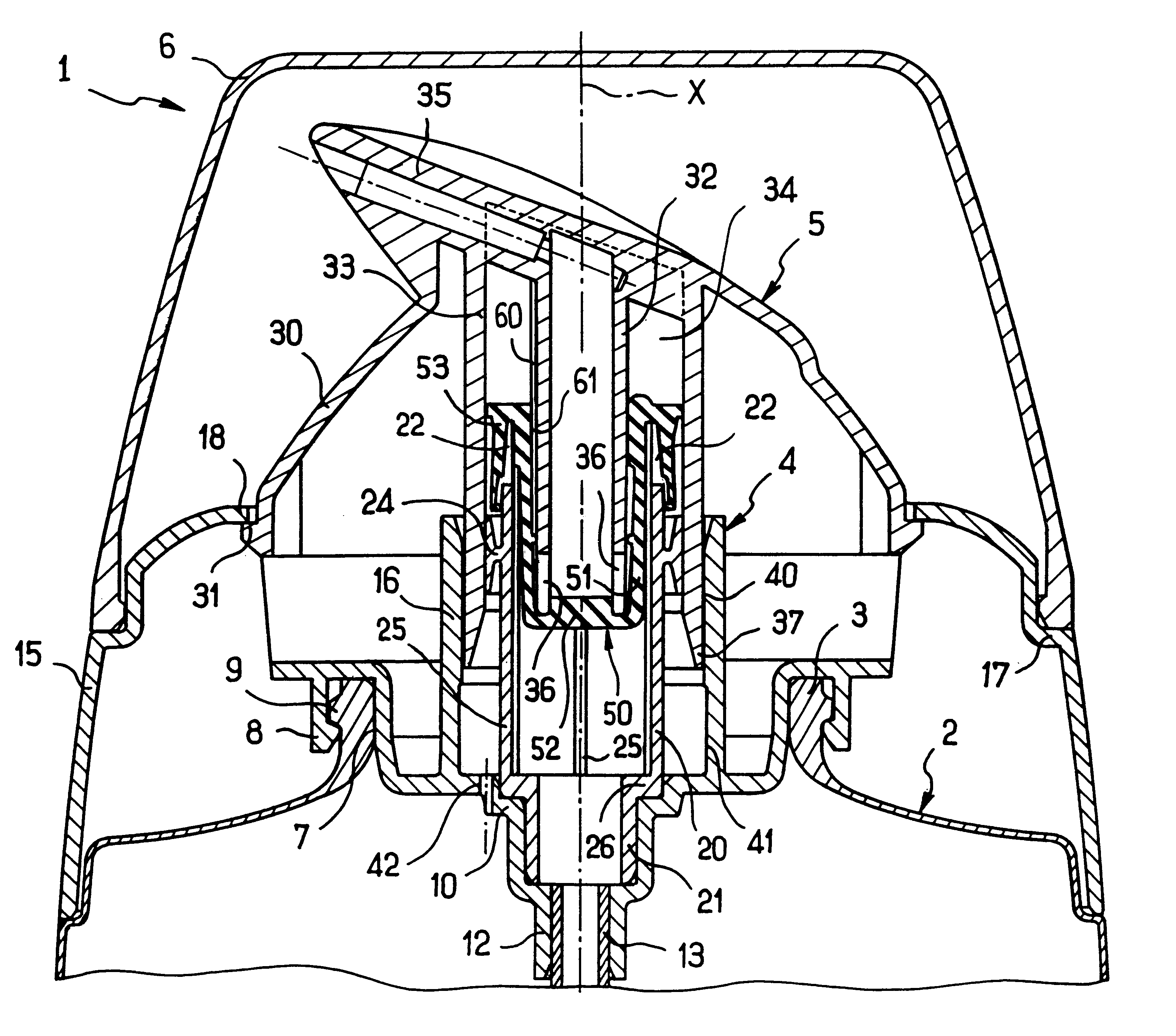
FIG. 1 shows a receptacle 1 comprising a tank-forming body 2 of which only the top end is shown in the drawing, defining a neck 3 on which a support 4 is snap-fastened.

The support 4 guides a pushbutton 5 in sliding along an axis X, and it serves to mount a removable protective cap 6 covering the pushbutton 5 prior to first use.

The support 4 has a sealing skirt 7 bearing in leakproof manner against the inner surface of the neck 3.

The sealing skirt 7 is extended radially, firstly outwards by fixing tabs 8 snap-fastened on an annular rim 9 of the neck 3, and secondly inwards in the form of a stepped wall 10 defining an endpiece 12 for connecting a dip tube 13, shown in part in the drawing.

An outer skirt 15 and a guide skirt 16 are integrally formed together with the sealing skirt 7, the fixing tabs 8, and the stepped wall 10 by molding a plastics material.

The outer skirt 15 extends around the neck 3 of the receptacle and presents a shoulder 17 on which the protective cap 6 bears.

The to...


PUM


Abstract

A pump of type comprising a moving member mounted to move relative to a support, the moving member having a central duct into which the substance to be dispensed penetrates via at least one opening, the support co-operating with the moving member to define a variable volume pump chamber around said central duct, the pump also having a diaphragm having a central portion in which said central duct is inserted, the diaphragm being organized in such a manner as to isolate the pump chamber from the opening(s) of the central duct when the volume of the pump chamber increases and the substance is sucked into it. At least one of the central duct and the central portion of the diaphragm includes an annular bulge that is suitable, when the volume of the pump chamber increases, for bearing in leakproof manner on the other of the central portion and the central duct of the diaphragm, so as to isolate the pump chamber from the opening(s) of the central duct.

Description

The present invention relates to a pump and to a receptacle containing a liquid, for example a cosmetic cream, and fitted with such a pump.French patent 2 728 809 discloses a pump comprising a pushbutton displaceably mounted on a support which is secured to the receptacle containing the substance to be dispensed, the pushbutton having a circularly cylindrical central duct provided with radial openings at its bottom end, the support defining an annular pump chamber of variable volume around said duct. A diaphragm made of elastomer is mounted on the support. The diaphragm has a circularly symmetrical central portion in the form of a sleeve that is open at its top end and closed at its bottom end. The central duct of the pushbutton is inserted in the diaphragm until it bears against the end wall of the sleeve. The diaphragm constitutes a resilient return member enabling the pushbutton to be returned to its initial position after a quantity of substance has been dispensed.During the ret...

Claims


Application Information

Patent Timeline
Patent Type & Authority Patents(United States)
IPC IPC(8): B05B11/00F04B9/14B65D47/34F04B43/02F16J3/02
CPCB05B11/00B05B11/3004B05B11/3064B05B11/3076B05B11/0044B05B11/1004B05B11/1061B05B11/1064B05B11/1076
Inventor BONNINGUE, PHILIPPEBEHAR, ALAIN
Owner LOREAL SA
Why Eureka
Try Eureka