Tank cap and fuel tank with the same

a tank cap and fuel tank technology, applied in the direction of caps, liquid handling, packaged goods, etc., can solve the problems of poor operability of the tank cap, user-imposed complicated operation, and troublesome, and achieve the effect of convenient positioning

Inactive Publication Date: 2001-10-30
TOYODA GOSEI CO LTD
View PDF10 Cites 39 Cited by
  • Summary
  • Abstract
  • Description
  • Claims
  • Application Information

AI Technical Summary

Benefits of technology

is thus to provide a tank cap that closes a tank opening by a single rotating o...

Problems solved by technology

In the prior art structure discussed above, since many rotations of the tank cap are required to close the fuel supply inlet, this is rather troublesom...

Method used


Image

  • Tank cap and fuel tank with the same
  • Tank cap and fuel tank with the same
  • Tank cap and fuel tank with the same

Examples


first embodiment

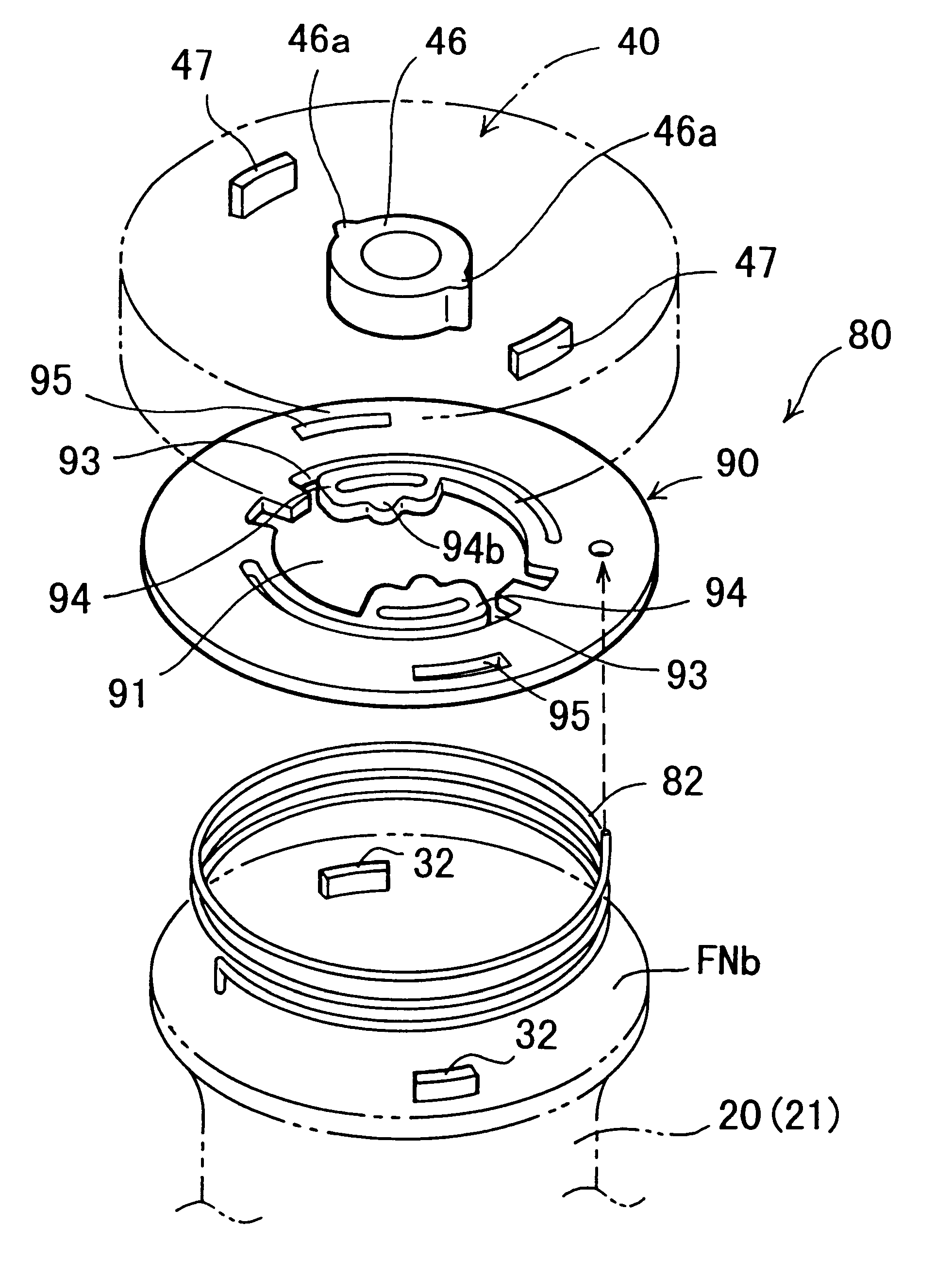
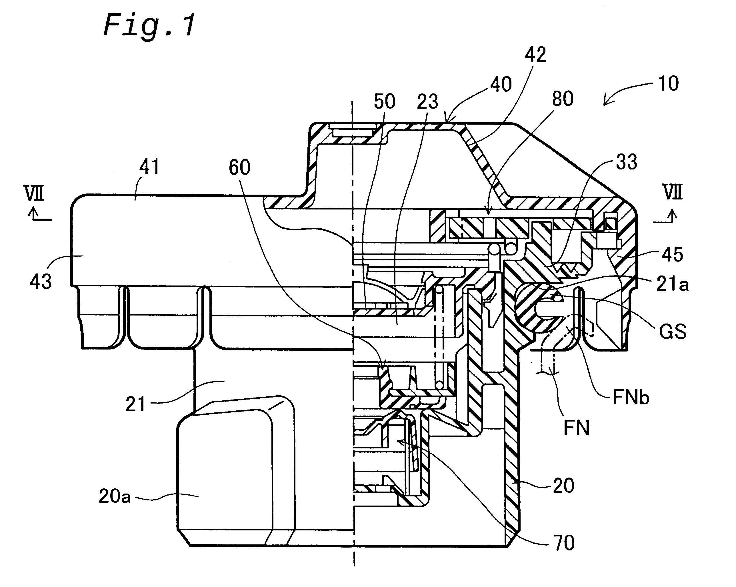
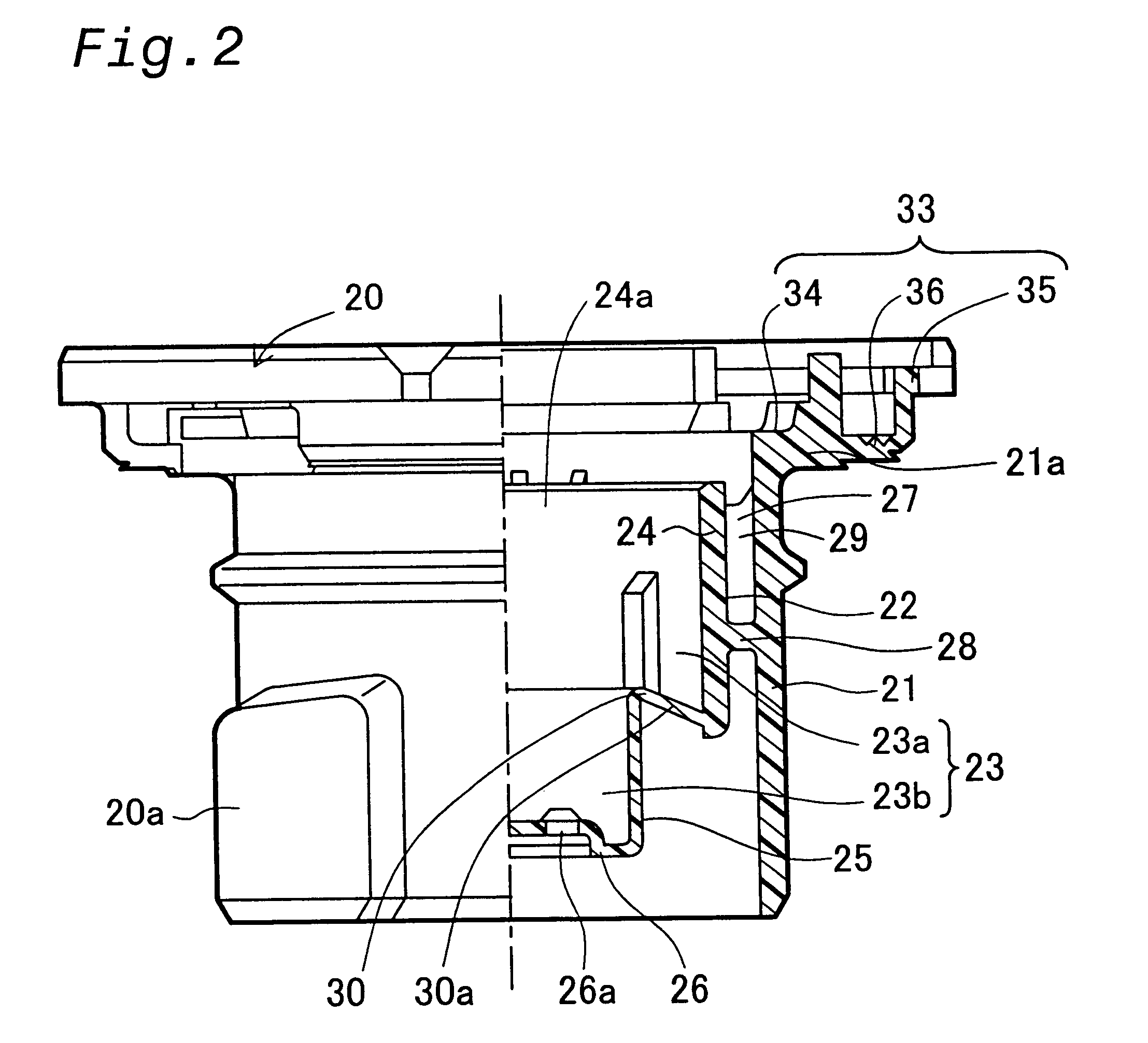
FIG. 1 is a semi-sectional view illustrating a tank cap 10 in a first embodiment according to the present invention. The tank cap 10 is attached to a filler neck FN having a fuel supply inlet FNb (tank opening), through which a supply of fuel is fed to a fuel tank (not shown). The tank cap 10 includes a casing main body 20 made of a synthetic resin material such as polyacetal, a cover 40 mounted on an upper portion of the casing main body 20, which is made of a synthetic resin material, such as nylon, and works like a handle, an inner cover 50 that closes an upper opening of the casing main body 20 to define a valve chest 23, a positive pressure valve 60, and a negative pressure valve 70 that are accommodated in the valve chest 23 and work as pressure control valves, a torque mechanism 80, and a gasket GS set on an upper circumference of the casing main body 20 to seal the casing main body 20 against the filler neck FN.

The elements of the tank cap 10 in this embodiment are described...

second embodiment

In the torque mechanism 180 of the second embodiment, the spring 182 accumulates the pressing force when a clockwise rotational torque is applied to the cover 140 to close the tank cap and causes the cover engagement projection 146a to ride over the plate engagement element 194b. When the user of the handle 142 of the cover 140, the accumulated pressing force of the spring 182 returns the positional relationship between the cover engagement projection 146a and the plate engagement element 194b to the initial state. This arrangement keeps the positional relationship that gives the user a feeling of attachment through an audible click in only one position. This facilitates the positioning of the handle 142 of the cover 140 relative to the casing engagement element 120a of the casing main body 120 and thereby simplifies the closing operation of the fuel supply inlet FNb of the filler neck FN.

Since there are practically no lost motions for returning the cover 140 to the initial position...


PUM

PropertyMeasurementUnit
Forceaaaaaaaaaa
Angleaaaaaaaaaa
Circumferenceaaaaaaaaaa

Abstract

A fuel cap is set on a tank opening and includes a casing main body, a cover, and a torque mechanism. The torque mechanism includes a cover engagement projection disposed on the cover, a torque plate having a plate engagement element, and a spring. When the cover is rotated in a closing direction of the tank opening, the cover engagement projection is released from the plate engagement element under a certain rotational torque to provide the user with the feeling of a click. When the cover is rotated in an opening direction of the tank opening, on the other hand, the cover engagement projection is released from the plate engagement element under a smaller rotational torque. This arrangement enables the spring to accumulate the pressing force and release the accumulated pressing force. The release of the accumulated pressing force causes the positional relationship between the cover and the casing main body to an initial state.

Description

1. Field of the InventionThe present invention relates to a tank cap having a torque mechanism to close a tank opening by a predetermined rotational torque and a fuel tank with the tank cap attached thereto.2. Description of Related ArtA known tank caps attached to a fuel tank of an automobile is disclosed in Japanese Patent Publication Gazette No. 6-88606. FIG. 36 is a sectional view illustrating a prior art tank cap 300. The tank cap 300 includes a plastic casing main body 302 that is screwed to a fuel supply inlet FNb of a fuel tank (not shown), a cover 330 that is attached to the casing main body 302, and a negative pressure valve 340 that is accommodated in a valve chest 304 formed in the casing main body 302 and regulates the pressure in the fuel tank. The negative pressure valve 340 includes a rubber valve disk 342, a valve support member 346 that has an opening 346a into which the valve disk 342 is fit, and a spring 348 that presses the valve disk 342. When the differential ...

Claims


Application Information

Patent Timeline
IPC IPC(8): B60K15/04
CPCB60K15/0406Y10S220/33
Inventor HAGANO, HIROYUKINAKAGAWA, MASAYUKI
Owner TOYODA GOSEI CO LTD
Why Eureka
Try Eureka