3D prestack seismic data migration method

a technology of prestack seismic data and migration method, which is applied in the direction of instruments, measurement devices, scientific instruments, etc., can solve the problems of reducing the calculation time required by a factor of several tens, complicated arrival time calculation, and general cost of calculation tim

a technology of prestack seismic data and migration method, which is applied in the direction of instruments, measurement devices, scientific instruments, etc., can solve the problems of reducing the calculation time required by a factor of several tens, complicated arrival time calculation, and general cost of calculation tim

US6311133B1Inactive Publication Date: 2001-10-30INST FR DU PETROLE

Image

  • 3D prestack seismic data migration method
  • 3D prestack seismic data migration method
  • 3D prestack seismic data migration method

Examples


Embodiment Construction

Definitions, Notations and Hypotheses Required

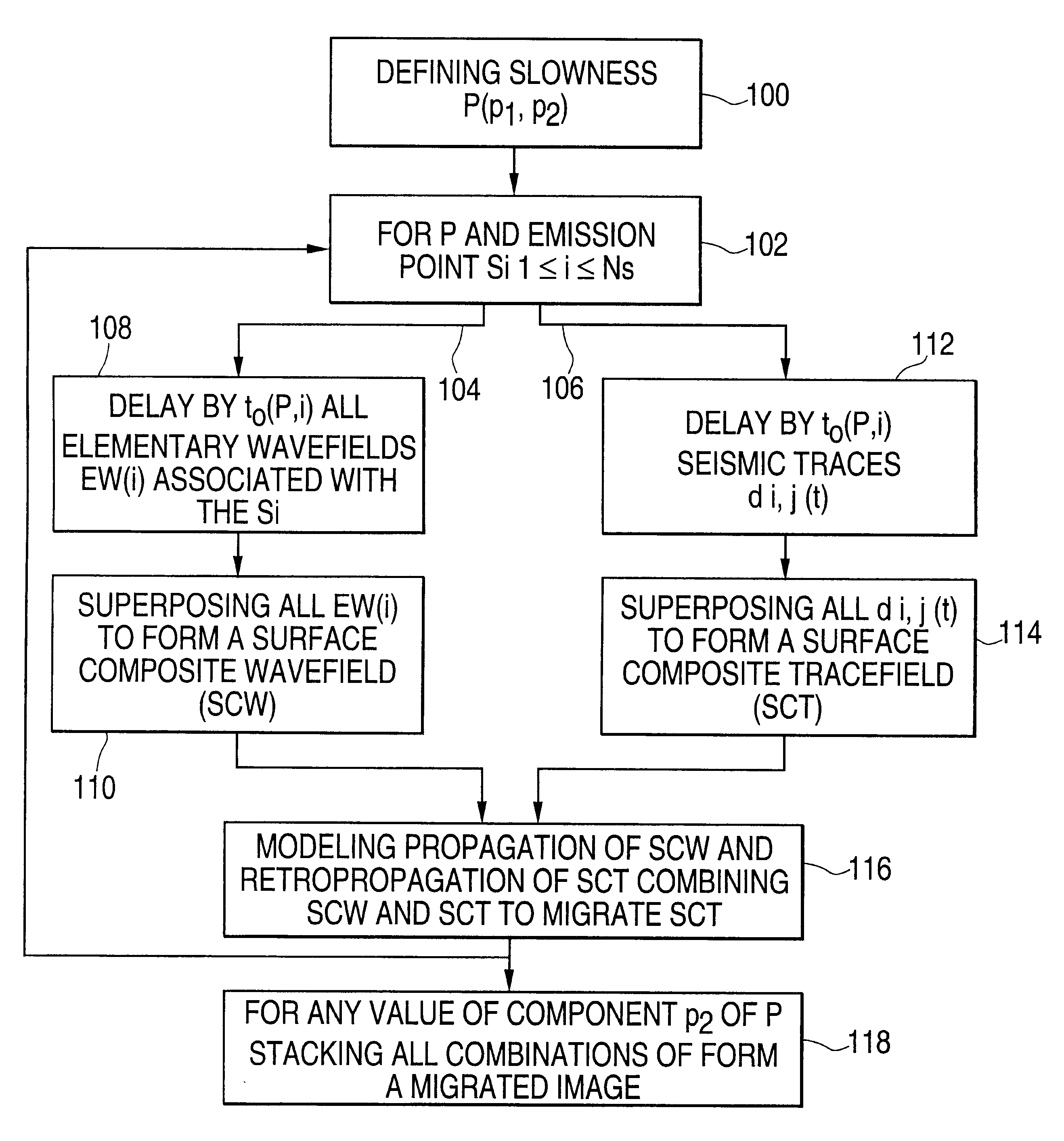
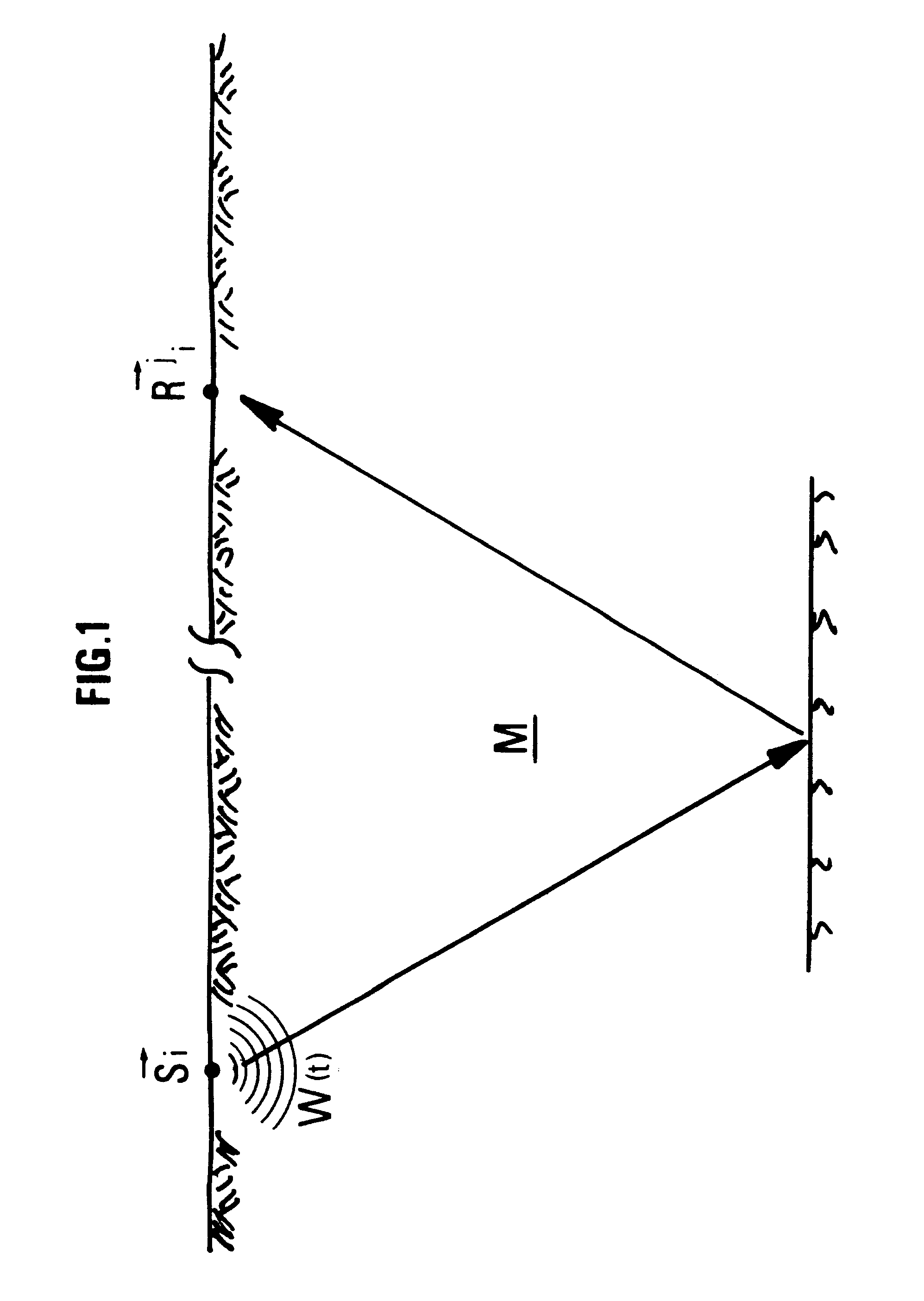
The method according to the invention performs migration of seismic data for imaging an underground zone M, the seismic data being obtained after a series of N.sub.s seismic cycles, each one (FIG. 1) comprising emission of a seismic signal W(t) from a point of emission S.sub.i with 1.ltoreq.i.ltoreq.N.sub.s, reception, by seismic receivers placed in positions R.sup.j.sub.i, of the seismic signals reflected by the zone discontinuities and recording of the various signals received by each seismic receiver as a seismic trace d.sup.j.sub.i (t). It is assumed that each seismic source emits the same signal W(t), since such a situation can always be obtained by suitable preprocessing of the data such as deconvolution.

The term profile refers to a set of aligned points of emission and it is assumed that all the signal acquisitions are performed using parallel emission profiles. It is assumed that, for each source, the receivers are located on the...


PUM


Abstract

A prestack migration method allowing imaging of an underground zone, for a given velocity model of arbitrary complexity. By means of conventional wave propagation and retropropagation modelling tools, the method allows to obtain elementary migrated images associated with the values assumed by a parameter and the sum of the images obtained for the different values of the parameter (post-migration stacking), in the depth domain as well as in the time domain. This migration is obtained at an attractive price (calculation cost) because it is independent of the volume of the results calculated and of the number of seismic traces recorded. Only the volume of the zone in which the waves are propagated, the complexity of the events to be imaged and the desired accuracy have an effect on the calculation cost. Volume images are thus obtained by taking account of all the seismic traces. It is thus possible to implement a plane wave migration procedure in cases where acquisition does not allow synthesis of the subsurface response to a plane wave excitation, a response required from the outset in conventional plane wave migration algorithms. The method can be applied for imaging of geologic interfaces or heterogeneities of a part of an underground zone.

Description

1. Field of the InventionThe present invention relates to a method allowing to perform prestack migration of recorded seismic events for imaging a part of an underground zone.2. Description of the Prior ArtPrestack migration is a conventional method of processing seismic data. The technique generally consists, knowing the value of a wavefield at a known depth, on the surface for example, and a model of the distribution of the wave propagation velocities in the zone, in modelling the propagation of the source field and the retropropagation of the recorded reflection data and in seeking phase coherences between these two modelled fields.There are three main prestack migration types:shotpoint migration: the source field is the vibrating state generated by the shotpoint and the reflection data are the response of the subsurface to this source field;plane wave migration, also called common illumination angle migration: the source field is the plane wave considered and the reflection data...

Claims


Application Information

Patent Timeline
30 Oct 2001
Publication
US6311133B1
IPC
G01V1/28; G01V1/30
CPC
G01V1/301
Inventors
LAILLY, PATRICK; DUQUET, BERTRAND