Compact, high-power microwave phase shifter

a phase shifter and microwave technology, applied in the field of phased array antennas, can solve the problems of large ferrite phase shifter, high cost, and inability to meet the requirements of liquid cooling,

Inactive Publication Date: 2001-11-06
RAYTHEON CO
View PDF1 Cites 7 Cited by
  • Summary
  • Abstract
  • Description
  • Claims
  • Application Information

AI Technical Summary

Problems solved by technology

However, most state of the art phased array antennas for radar applications require phase shifters that switch in the sub-millisecond range.
However, there are current directed energy system development programs that require a phased array antenna capable of radiating extremely high power.
Unfortunately, there are no compact phase shifters currently available for these applications.
However, this ferrite phase shifter is large, heavy, requires liquid cooling and is very expensive.

Method used


Image

  • Compact, high-power microwave phase shifter
  • Compact, high-power microwave phase shifter
  • Compact, high-power microwave phase shifter

Examples


Embodiment Construction

Illustrative embodiments and exemplary applications will now be described with reference to the accompanying drawings to disclose the advantageous teachings of the present invention.

While the present invention is described herein with reference to illustrative embodiments for particular applications, it should be understood that the invention is not limited thereto. Those having ordinary skill in the art and access to the teachings provided herein will recognize additional modifications, applications, and embodiments within the scope thereof and additional fields in which the present invention would be of significant utility.

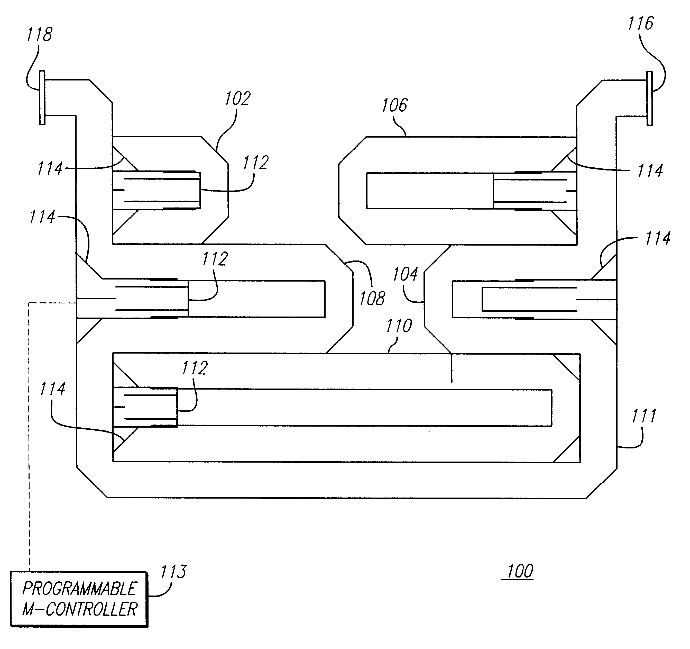
FIG. 1 shows a cross-sectional view of an exemplary embodiment of a digital phase shifter 100 constructed in accordance with the teachings of the present invention. The digital phase shifter 100 includes five switchable U-shaped waveguide sections 102, 104, 106, 108 and 110 of various path lengths disposed within a primary waveguide section 111. The primary wave...


PUM


Abstract

A phased array antenna including at least one configurable phase shifter. The configurable phase shifter includes a U-shaped primary waveguide section and multiple switchable waveguide U-shaped sections disposed within the primary section. The switchable waveguide sections include a plunger in the U-shaped waveguide section and one or more solenoids attached to the plunger, driving the plunger in and out such that the switches can be actuated in less than 100 milliseconds. The plunger and the switchable waveguide section are shaped such that the waveguide height is constant in the U-shaped waveguide section when the switch is closed and constant in the primary waveguide section when the switch is open, thereby minimizing return loss. The U-shaped primary waveguide section includes an input port and an output port at opposite sides. A radiating slot is located at the bottom face of the U-shaped primary waveguide section. The radiating slot may be formed in a detachable plate attached to the bottom the U-shaped primary waveguide section. Further, multiple one configurable phase shifters may be cascaded to form a traveling wave phased array antenna.

Description

1. Field of the InventionThe present invention relates to phased array antennas. More specifically, the present invention relates to digital phase shifters for high power radio frequency phased array antennas.2. Description of the Related ArtAn integral component of a wide-scan phased array antenna is a compact phase shifter. However, most state of the art phased array antennas for radar applications require phase shifters that switch in the sub-millisecond range.In what is commonly referred to as a digital phase shifter, the length of the phase shifter is configurable from different lengths or sections of waveguides that can be selectively switched in or out. Typically, the various sections are lengths that are proportional to each other by factors of 2. For example, one length may be twice as long as another, second length. Yet a third length may be twice as long as the second length and so on. Thus, the various sections may be selectively switched in or out, thereby being combine...

Claims


Application Information

Patent Timeline
Patent Type & Authority Patents(United States)
IPC IPC(8): H01Q3/30H01Q3/34H01Q3/32H01P1/18
CPCH01P1/182H01Q3/32H01Q3/34
Inventor BROWN, KENNETH W.GIANCOLA, VINCENT
Owner RAYTHEON CO
Why Eureka
Try Eureka