Microwave phase shifter based on plane type left hand microstrip transmission line

A technology of microstrip transmission line and microwave phase shifter, which is applied in the direction of waveguide devices, electrical components, circuits, etc., can solve the problems of large volume, small power capacity, and large loss, and achieve small volume, large power capacity, and low loss Effect

Inactive Publication Date: 2011-09-14
UNIV OF SCI & TECH OF CHINA
View PDF0 Cites 2 Cited by
  • Summary
  • Abstract
  • Description
  • Claims
  • Application Information

AI Technical Summary

Problems solved by technology

[0011] The purpose of the present invention is to overcome the shortcomings of the existing microwave phase shifter such as: large volume, large loss, small power capacity, etc., to provide a compact structure based on the structure of the planar left-handed microstrip transmission line. Power Capacity Microwave Phase Shifter

Method used


Image

  • Microwave phase shifter based on plane type left hand microstrip transmission line
  • Microwave phase shifter based on plane type left hand microstrip transmission line
  • Microwave phase shifter based on plane type left hand microstrip transmission line

Examples


Embodiment 1

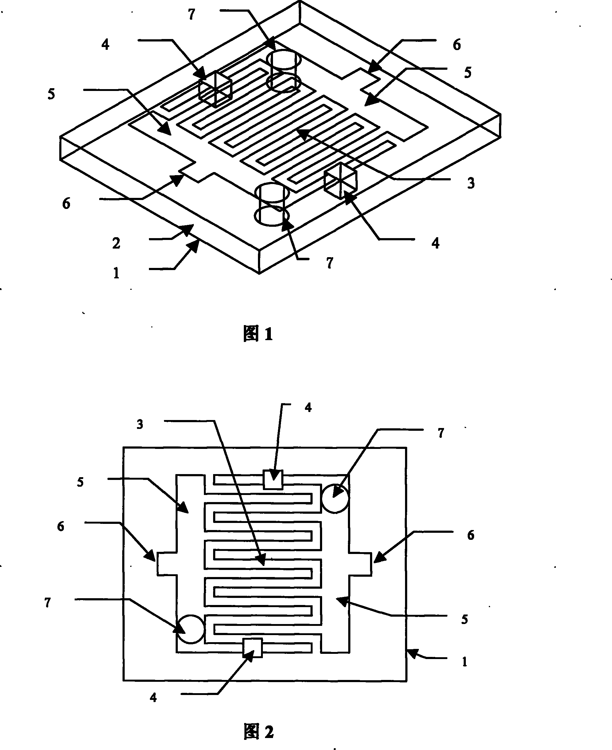
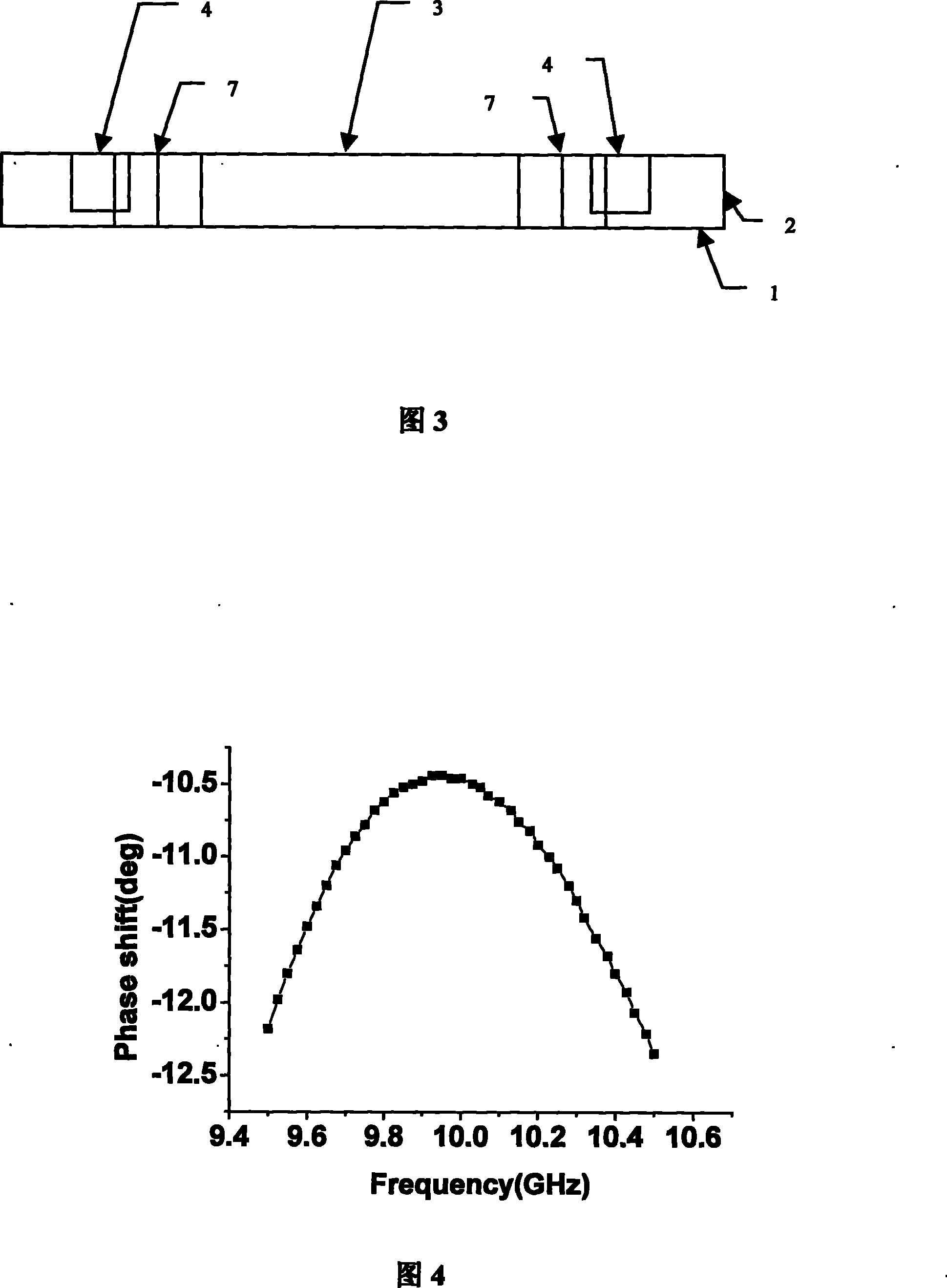
[0039] see figure 1 , figure 2 and image 3 , the left-hand microstrip transmission line phase shifter is designed on the PCB board, using Rogers RT / TMM 10i alumina dielectric substrate with a layer area of ​​8mm×6mm; the first and third layers of the PCB are conductor copper, and the thickness is ( 0.004mm), the third layer of metal constitutes the ground 1 of the left-hand transmission line, the middle layer is a dielectric layer 2 with a dielectric constant of 9.8, and its thickness is 0.254mm; Make interdigitated capacitor 3 in the area of ​​8mm×6mm in the center of the first layer conductor copper area 2.28mm×1.9mm. Width 0.1mm, interdigital spacing 0.1mm, interdigital length 1.14mm, one on each of the outermost interdigital fingers at both ends, and a pair of APD0810-000 PIN switches 4 from SKYWPRKS Company (normal temperature 25 The power capacity at ℃ is 2.5W), the switch position is 0.41mm away from the root of the interdigitation, the switch size is 0.35mm×0.35mm...

Embodiment 2

[0043] see Figure 7 , Figure 8 and Figure 9 , the left-hand microstrip transmission line phase shifter is designed on the PCB board, using Rogers RT / duroid 5880 dielectric substrate with a layer area of ​​8mm×6mm; the first and third layers of the PCB board are conductor copper, and the thickness is (0.004mm) , the ground 1 of the left-hand transmission line is composed of the third layer of metal, and the middle layer is a dielectric layer 2 with a dielectric constant of 2.2, and the thickness is 0.254mm; Make an interdigitated capacitor 3 in the center of the copper conductor on the first layer of 3.915mm×2.3mm, and the number of interdigitated fingers is 4, that is, there are 4 interdigitated fingers in each sheet, 2 sheets of interdigitated fingers are placed in parallel, and the width of the inner 4 interdigitated fingers 0.1mm, interdigital length 3.415mm, interdigital spacing 0.1mm; sublateral 2 interdigital width 0.1mm, interdigital length 3.415mm, and inner inter...

Embodiment 3

[0047] see Figure 13 , Figure 14 and Figure 15 , the left-hand microstrip transmission line phase shifter is designed on the PCB board, using Rogers RT / duroid 5880 dielectric substrate with a layer area of ​​8mm×6mm; the first and third layers of the PCB board are conductor copper, and the thickness is (0.004mm) , the ground 1 of the left-hand transmission line is composed of the third layer of metal, and the middle layer is a dielectric layer 2 with a dielectric constant of 2.2, with a thickness of 0.254mm; an interdigitated capacitor is made in the center of the first layer of conductor copper in an area of ​​3.915mm×6.7mm 3. The logarithm of interdigitation is 4, that is, each interdigitation has 4 interdigitations, 2 interdigitation interdigitations are placed in parallel, the width of the inner 4 interdigitations is 0.1mm, the length of interdigitation is 3.415mm, and the distance between interdigitations is 0.1mm; the second outer interdigitation is 2 The interdigit...


PUM


Abstract

The invention relates to plane left-hand microstrip transmission line structure based microwave phrase shifter, solving the problems of big volume, large consumption, small power capacity, etc. of the prior microwave phrase shifter. The microwave phrase shifter of the invention is formed by arranging PIN switches on a left-hand microstrip transmission line unit. The details of the proposal are that: a pair of PIN switches is arranged on a selected pair of side strips or of interdigital strips arranged on corresponding positions; a signal input port and a signal output port are respectively positioned on the pair of side strips. As a result, only a small part of the current passing through the whole phrase shifter passes through the PIN switches arranged on a single interdigital strip or on the side strips, thereby power capacity of the phase shifter is improved greatly; in addition to the high power capacity, the phrase shifter has various advantages such as small consumption, small volume, fast shifting speed, convenient manufacture, capacity for easy integration with an MMIC circuit. The invention has great advantage in terms of application in radar and phrased antenna array.

Description

technical field [0001] The invention relates to a microwave phase shifter, specifically a microwave phase shifter based on a planar left-handed microstrip transmission line. Background technique [0002] Microwave phase shifters are used in many fields, such as radar systems, satellite communication systems and phased array antenna arrays. There are many types of phase shifters. According to the materials used, there are generally five categories: ferrite phase shifters, ferroelectric phase shifters, semiconductor diode phase shifters, gallium arsenide MMIC phase shifters and MEMS phase shifters. phase device. [0003] In 1991, Artech house published "Microwave and Millimeter Wave Phase Shifters". The first volume of the book, Dielectric and Ferrite Phase Shifters, introduced the main types, design, production and application of ferrite phase shifters in detail. The ferrite phase shifter mainly uses an external magnetic field to change the magnetic permeability of the ferr...

Claims


Application Information

Patent Timeline
Patent Type & Authority Patents(China)
IPC IPC(8): H01P1/19H01P1/18
Inventor 朱旗张君吴磊芦伟毛文辉盛升
Owner UNIV OF SCI & TECH OF CHINA
Why Eureka
Try Eureka