A stable microwave oscillator

A technology of photoelectric oscillator and microwave amplifier, which is applied in the direction of solid-state lasers, etc., can solve the problems that stability and spurious mode suppression cannot be taken into account at the same time, and the phase noise deterioration of OEO oscillation signals, etc., achieves simple structure, high signal-to-noise ratio, and easy Achieved effect

Inactive Publication Date: 2015-12-30
SOUTHEAST UNIV
View PDF8 Cites 2 Cited by
  • Summary
  • Abstract
  • Description
  • Claims
  • Application Information

AI Technical Summary

Problems solved by technology

[0008] In order to overcome the limitations of the existing OEO technical solutions and solve the defects that the existing OEO solutions cannot take into account both stability and spurious mode suppression or will introduce additional noise to cause the phase noise deterioration of the OEO oscillating signal, the present invention provides a low additional noise , OEO technical solution that can take into account stability and stray mode suppression, simple structure and easy to implement

Method used


Image

  • A stable microwave oscillator
  • A stable microwave oscillator
  • A stable microwave oscillator

Examples


Embodiment 1

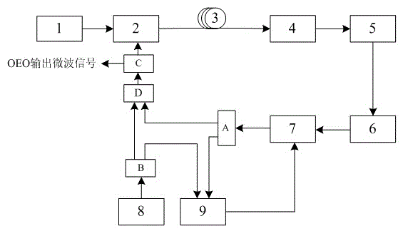
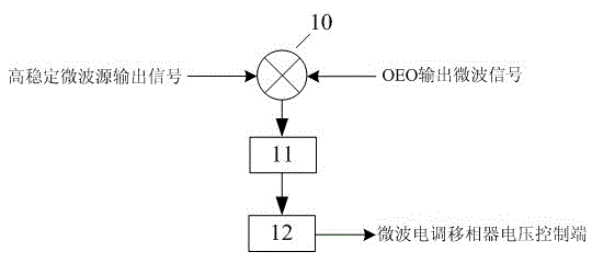
[0025] according to figure 1 and figure 2A stable optoelectronic oscillator shown, mainly consists of a laser 1, an electro-optic modulator 2, a long fiber 3, a photodetector 4, a microwave amplifier 5, an electrical band-pass filter 6, an electrical regulator Microwave phase shifter 7, a high stability microwave source 8, a 2×1 directional coupler D, the first 1×2 power splitter or the first 1×2 directional coupler A, the second 1×2 power splitter or The second 1×2 directional coupler B, the third 1×2 power splitter or the third 1×2 directional coupler C, and the phase-locking control module 9 are composed, wherein the phase-locking control module 9 is mainly composed of a mixer 10. It is composed of an electric low-pass filter 11 and a servo controller 12, the output end of the mixer 10 is connected to the input end of the electric low-pass filter 11, and the output end of the electric low-pass filter 11 is connected to the servo control Input of module 12. The output en...

Embodiment 2

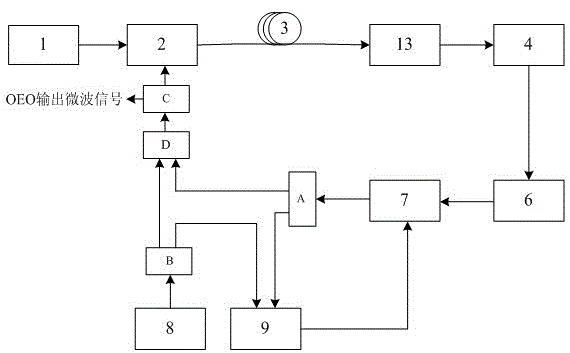
[0028] according to figure 2 and image 3 A stable photoelectric oscillator shown is mainly composed of a laser 1, an electro-optic modulator 2, a long fiber 3, a photodetector 4, an optical amplifier 13, an electrical bandpass filter 6, an electrical modulator Microwave phase shifter 7, a highly stable microwave source 8, a 2x1 directional coupler D, a first 1x2 power divider A, a second 1x2 power divider B, a third 1x2 power divider C and The phase-locked control module 9 is composed of a phase-locked control module 9, wherein the phase-locked control module 9 is mainly composed of a mixer 10, an electrical low-pass filter 11, and a servo controller 12, and the output end of the mixer 10 is connected to the electrical low-pass filter 12. The input end of the pass filter 11 and the output end of the electric low pass filter 11 are connected to the input end of the servo control module 12 . The output end of the laser 1 is connected to the optical input end of the electro-o...


PUM


Abstract

The invention discloses a stable photoelectric oscillator. The stable photoelectric oscillator comprises a laser device, an electro-optical modulator, a long optical fiber, a photoelectric detector, an amplifier, an electric band-pass filter, an electrically-controlled microwave phase shifter, a high-stability microwave source, a 2*1 wave combiner or directional coupler, a first 1*2 power divider or directional coupler, a second 1*2 power divider or directional coupler, a third 1*2 power divider or directional coupler and a phase locking control module, wherein the phase locking control module comprises a frequency mixer, an electric low pass filter and a servo control module, the output end of the frequency mixer is connected to the input end of the electric low pass filter, and the output end of the electric low pass filter is connected to the input end of the servo control module. According to the stable photoelectric oscillator, an electric injection of the external high-stability microwave source and a phase locking control mechanism are added based on a traditional single-loop OEO structure. Compared with the prior art, the stable photoelectric oscillator has the advantages that insertion loss of an optical link in a resonant cavity is not increased, the high signal to noise ratio of the photoelectric resonant cavity is maintained, and the structural complexity of the stable photoelectric oscillator is lower than that of an existing scheme. The stable photoelectric oscillator is easy to obtain.

Description

technical field [0001] The invention belongs to the technical field of microwave and optoelectronics, and in particular relates to a photoelectric oscillator. Background technique [0002] Optoelectronic Oscillator (OEO: Optoelectronic Oscillator) is a new type of oscillator that uses high quality factor (Q value) optical energy storage components to replace traditional microwave energy storage components. The phase noise of the signal is much smaller than that of current electrical oscillators. The basic structure of OEO was first proposed by X.SteveYao and LuteMaleki in 1994. It consists of a laser and consists of an electro-optic modulator, a long optical delay line (such as an optical fiber, etc.), a photodetector, a microwave amplifier, a bandpass The closed feedback loop formed by the filter, wherein the output signal of the band-pass filter is fed back to the microwave input end of the electro-optic modulator. In this structure, the vibration is first started by noi...

Claims


Application Information

Patent Timeline
Patent Type & Authority Patents(China)
IPC IPC(8): H01S1/02
Inventor 杨春洪俊曹哲玮
Owner SOUTHEAST UNIV
Why Eureka
Try Eureka