Synchronization scheme with adaptive reference frequency correction

a reference frequency correction and synchronization scheme technology, applied in the direction of synchronization arrangement, resonant circuits using central processing units, wireless communication, etc., can solve the problem that the crystal oscillator alone cannot provide a sufficiently constant frequency to meet the frequency stability requirements, the prior art solution has the disadvantage of additional cost and space, and the frequency deviations. problem, to achieve the effect of improving the synchronization scheme, the method and the apparatus

Active Publication Date: 2011-10-13
SNAPTRACK
View PDF30 Cites 12 Cited by
  • Summary
  • Abstract
  • Description
  • Claims
  • Application Information

AI Technical Summary

Benefits of technology

[0011]It is an object of the present invention to provide an improved synchronization scheme, method and apparatus, by means of which an exac

Problems solved by technology

However, crystal oscillators by themselves cannot provide a sufficiently constant frequency to meet the frequency stability requirements of the radio terminal.
Additionally, non-linearities in the control path of the reference oscillator may cause frequency deviations.
This prior art solution has the disadvantage of additional cost and space and reduced reliability.
However, in this solution, the exact reference frequency which is needed e.g. for processing of prot

Method used


Image

  • Synchronization scheme with adaptive reference frequency correction
  • Synchronization scheme with adaptive reference frequency correction
  • Synchronization scheme with adaptive reference frequency correction

Examples


Embodiment Construction

[0032]The preferred embodiment will now be described based on a synchronization of a mobile terminal to a synchronization information or synchronization signal emitted by a cellular network.

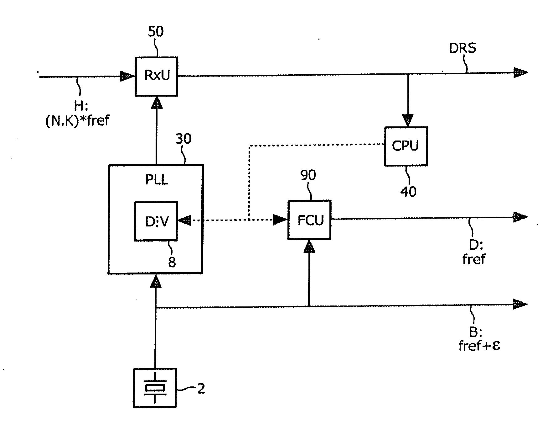
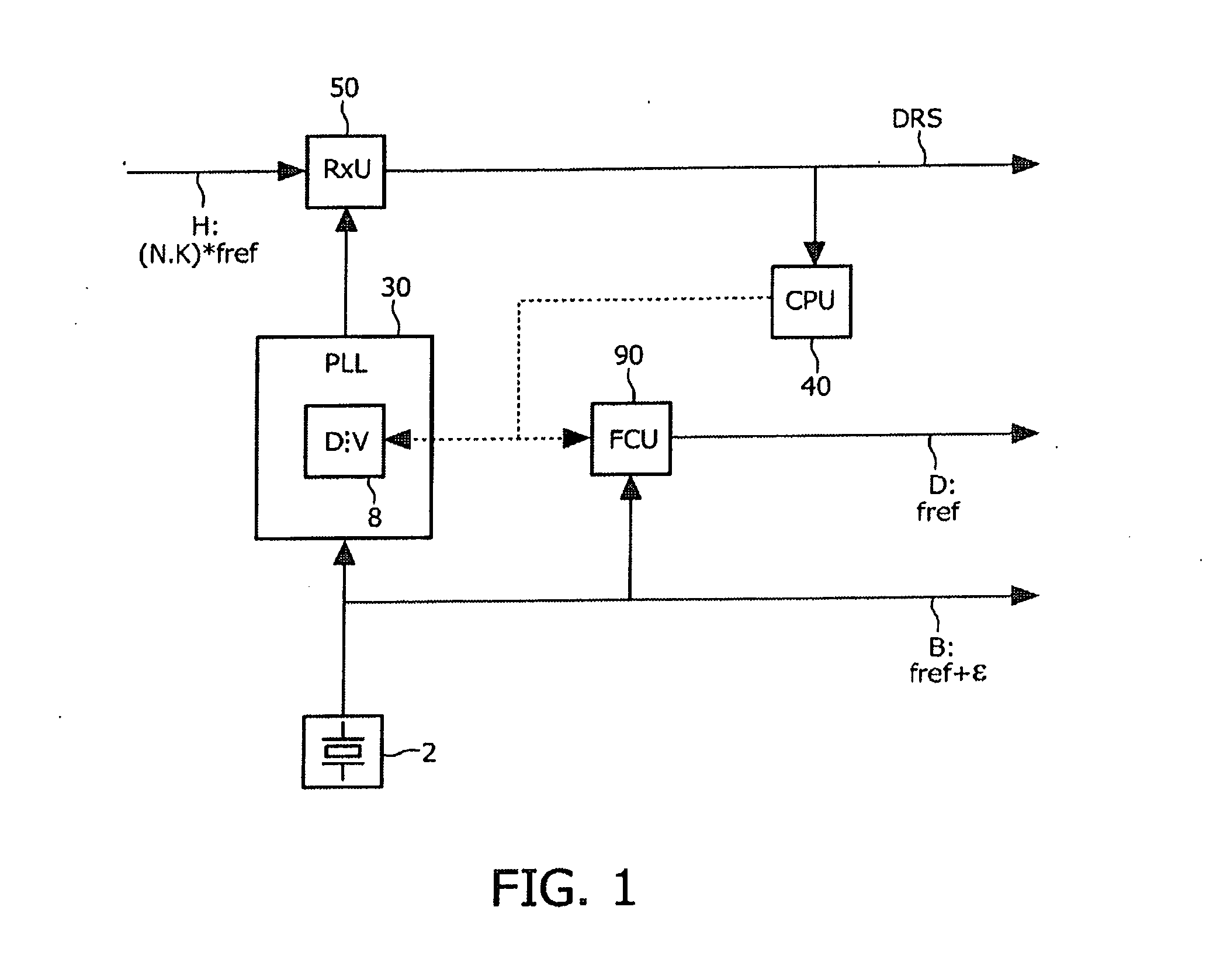
[0033]FIG. 1 shows a schematic block diagram indicating the synchronization mechanism underlying the preferred embodiment. The synchronization of the reference frequency in the mobile terminal or mobile user equipment is accomplished by deriving from a control information of a divider 8 of a phase locked loop (PLL) circuitry 30 a further control information for a frequency conversion unit 90. The PLL circuitry 30 is supplied with an uncorrected reference oscillator signal B. This uncorrected reference oscillator signal B for the phase locked loop circuitry 30 is generated by a simple crystal oscillator 2 having no means or circuitry for frequency control. The setting of the divider 8 and the frequency conversion unit 90 and their configuration is performed by a control unit or mechanism 40. This ...


PUM


Abstract

An apparatus and a method provide synchronization of an output signal to a synchronization information. The synchronization is accomplished by providing coupling of a correction control information that controls a signal generator, e.g. a phase locked loop arrangement or a direct digital synthesis arrangement, to its exact frequency to a frequency conversion unit that converts an uncorrected reference frequency to a correct or exact reference frequency. Thereby, the uncorrected reference frequency for the signal generator can be provided by a simple crystal oscillator without any frequency controller. The setting of the signal generator and the frequency conversion unit can be done in a predetermined sequence which enables a user equipment to synchronize its reference frequency to the synchronization information emitted by a communication network.

Description

BACKGROUND[0001]1. Technical Field[0002]The present invention relates to a method and apparatus for providing synchronization of an output signal to a reference signal, to be used for reference frequency synchronization in a mobile terminal, for example.[0003]2. Description of the Related Art[0004]Radio communication devices require generation of stable operating frequencies in order to function properly. Typically, stability has been obtained by using a crystal oscillator as a reference oscillator to provide a reference frequency. Specifically, local oscillators of radio terminals are phase-locked to the reference frequency. However, crystal oscillators by themselves cannot provide a sufficiently constant frequency to meet the frequency stability requirements of the radio terminal. In particular, the output frequency of a crystal oscillator varies over temperature. Additionally, non-linearities in the control path of the reference oscillator may cause frequency deviations.[0005]Rad...

Claims


Application Information

Patent Timeline
IPC IPC(8): H03L7/06H04W56/00
CPCH03J1/005H04L7/033H03L7/1974H03J7/065
Inventor NEUMANN, MARKUS
Owner SNAPTRACK
Why Eureka
Try Eureka