Oscillator circuit configuration

a technology of oscillator circuit and configuration, applied in the direction of oscillator generator, pulse generator, pulse technique, etc., can solve problems such as temperature fluctuation, and achieve the effect of preventing temperature, frequency and amplitude fluctuations

Inactive Publication Date: 2006-09-05
SYNERGY MICROWAVE CORP
View PDF12 Cites 13 Cited by
  • Summary
  • Abstract
  • Description
  • Claims
  • Application Information

AI Technical Summary

Benefits of technology

[0005]It is therefore the object of the invention to provide an oscillator circuit, in which the operating point can be kept constant by simple means, in order to prevent the temperature, frequency and amplitude fluctuations mentioned.
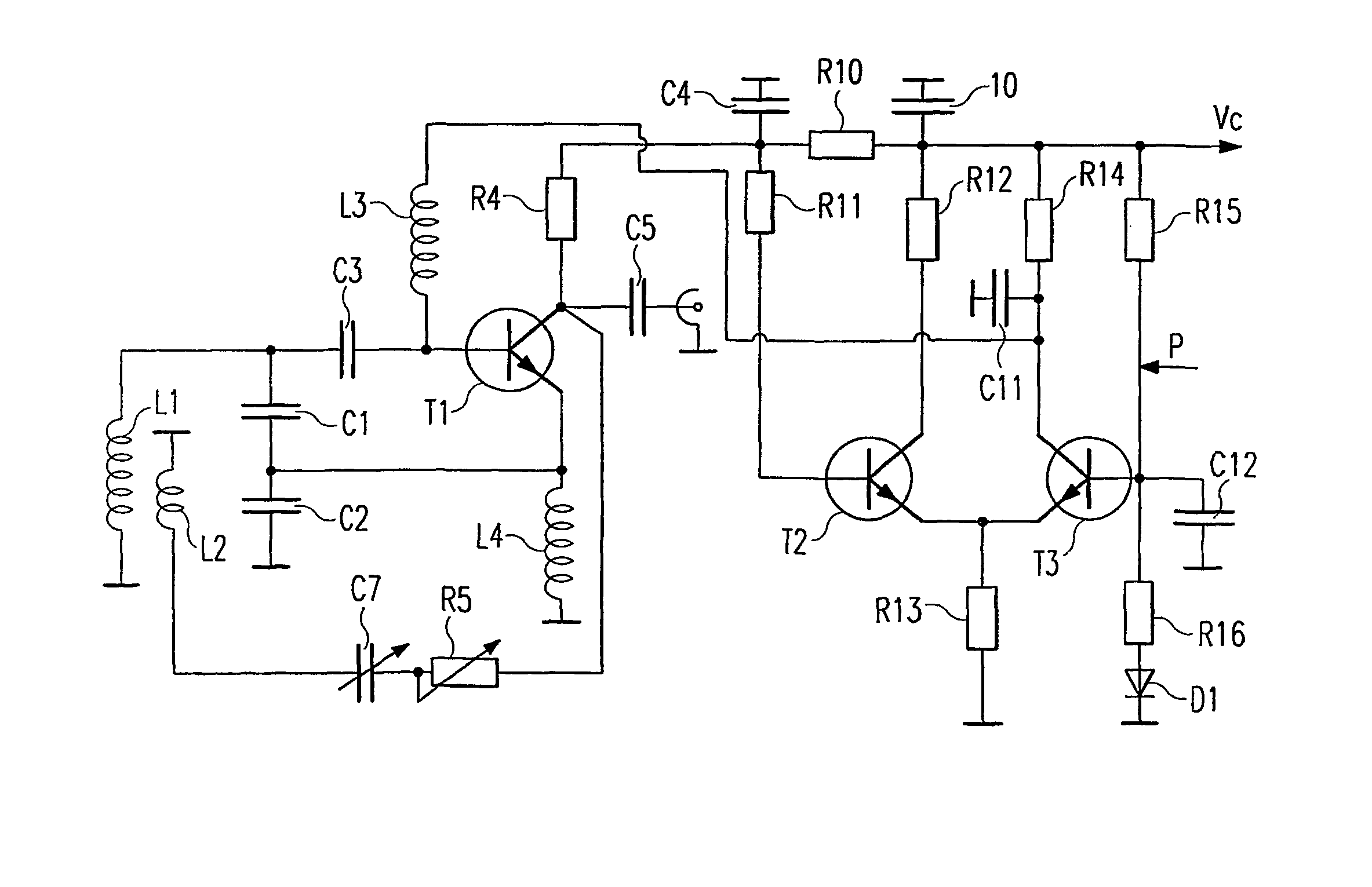
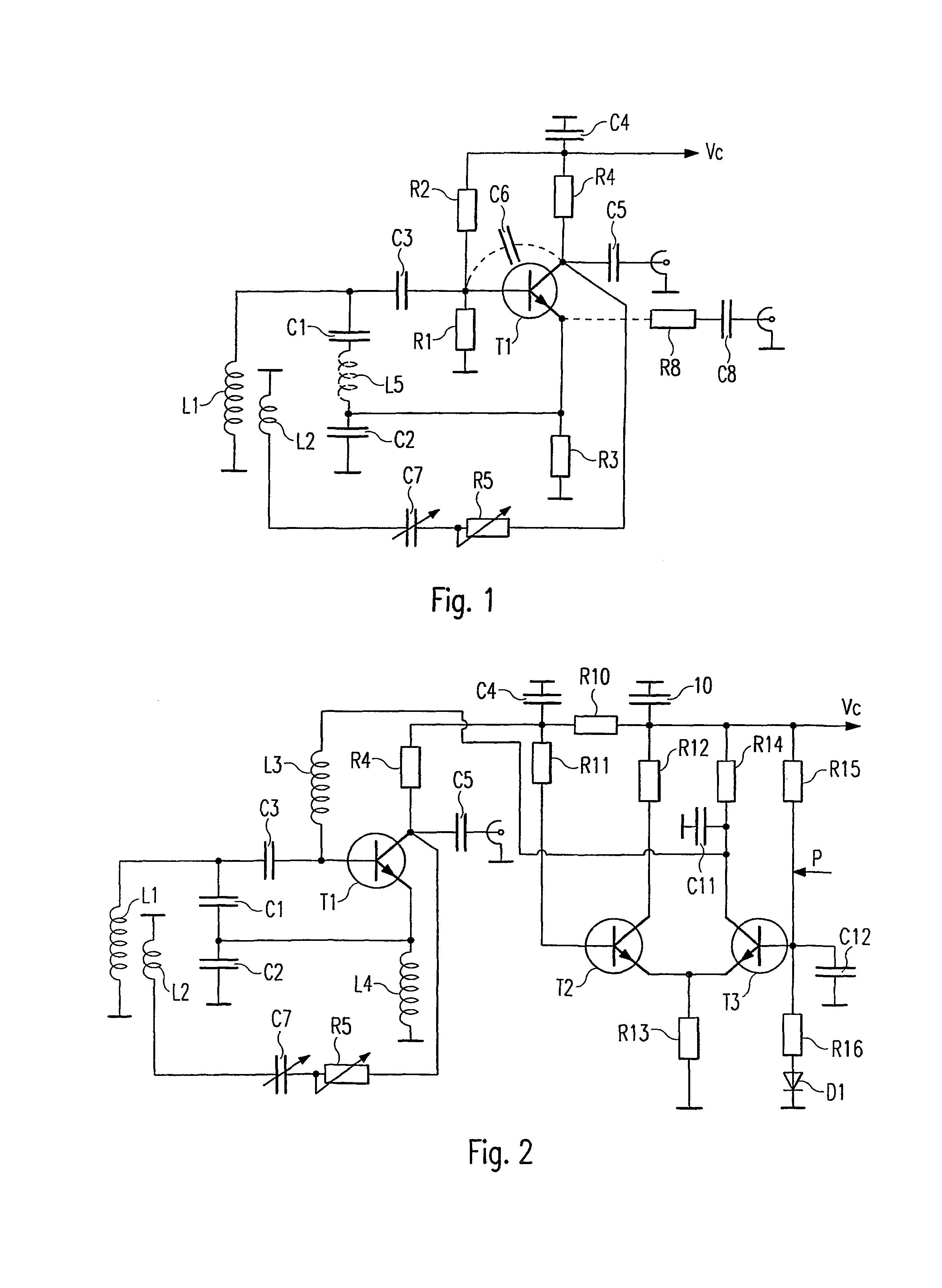
[0007]As a result of the additional compensation coil on the parallel resonant circuit, the interfering effect of the parasitical collector capacitance, which on the one hand consists of internal capacitance of the semi-conductor and possibly also capacitance of the housing and remaining structure, is compensated, thus no longer acting in parallel with the inductor of the parallel resonant circuit and as a result changing the frequency dependent on operating point. As a result of the measure according to the invention a change in frequency is thus prevented by changing the parasitical collector capacitance of the amplifier element and therefore an oscillator with high spectral purity is created.
[0008]In the case of Colpitts oscillators, the bipolar amplification transistor of which is operated in the collector circuit and the collector of which is earthed, although the parasitical collector capacitance acts without being amplified on the inductor of the parallel resonant circuit, the measure according to the invention is also advantageous in the case of such oscillator circuits. Particularly advantageous is the measure according to the invention however in the case of such oscillator circuits, for example Colpitts oscillators, in which the output signal is decoupled at the collector of the amplification transistor and therefore the collector is no longer earthed. The parasitical collector capacitance in this case is multiplied with the amplification coefficient on the collector and therefore increased many times over at the inductor of the parallel resonant circuit. However, it can be very easily suppressed according to the invention.
[0009]Another possibility for stabilizing the operating point and therefore for preventing the temperature, frequency and amplitude fluctuations mentioned as detailed in subclaim 3 according to the invention is to keep the collector current of the transistor constant with a controlled gain amplifier. This measure is especially advantageous in combination with an oscillator circuit according to claims 1 and 2, but can, however, also be very effective by itself. As a result of such regulation to keep the collector current constant, the operating point of the transistor is kept constant and at the same time AC components close to the carrier which are caused by internal interference sources of the transistor are fully stabilised. By stabilising the operating point it is also possible to prevent any changes in current conduction angle in the event of changes in frequency, which in turn would affect the operating point. As a result of stabilising the operating point in the event the oscillator becomes detuned, the output amplitude of the oscillator changes less than with known circuits, for example only by 1 dB. Not only slow changes are fully stabilised, but also changes over a bandwidth, which ranges from DC up to a limit frequency determined by the controlled gain amplifier. Thus relatively fast changes in the operating point of the transistor can also be fully stabilised and in this way interference modulation can be precluded. Therefore also amplitude noise and also any phase noise possibly produced as a result is reduced. It has proved especially advantageous, both for the amplifier element of the oscillator as well as for the amplifier elements of the control circuit to use transistors of the same type, for example bipolar transistors of the npn-type, which is possible by selecting the topology of the circuit accordingly.

Problems solved by technology

A problem with such oscillator circuits is temperature fluctuation, variations in frequency response as well as amplitude noise and phase noise resulting from this.

Method used


Image

  • Oscillator circuit configuration
  • Oscillator circuit configuration
  • Oscillator circuit configuration

Examples


Embodiment Construction

)

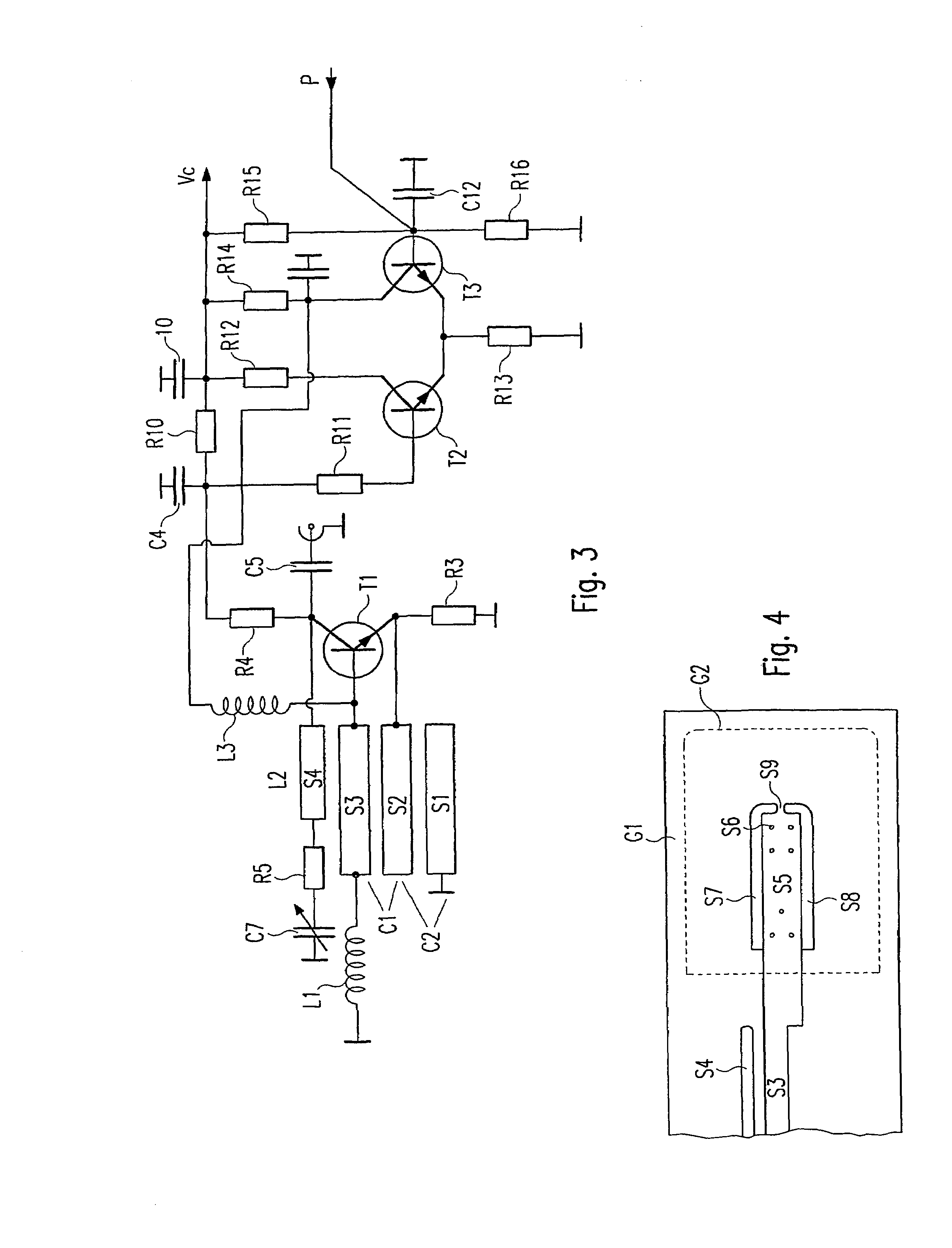
[0015]The invention is explained in more detail below by way of the embodiments shown in schematic drawings.

[0016]FIG. 1 shows the principle circuit diagram of a Colpitts oscillator with a parallel resonant circuit, consisting of an inductor L1 and the series circuit of two capacitors C1 and C2. A transistor T1 is used as an amplifier element, in the embodiment shown a bipolar npn-transistor. The resonant frequency of the oscillator is determined by L1 and C1 / C2. The operating point of the oscillator T1 is determined by the resistors R1, R2 and R3, through which also the supply voltage Vc is applied. If the output frequency is decoupled via the capacitor C5 on the collector of the transistor T1, a resistor R4 determining the output resistance is provided between collector and the capacitor C4. If decoupling occurs on the emitter of the transistor, as indicated by a dotted line in FIG. 1 through C8 and R8, this resistor R4 is superfluous and the collector of the transistor T1 is dir...


PUM


Abstract

The invention relates to an oscillator circuit configuration comprising in an LC-parallel oscillatory circuit and a transistor as an amplifying element. A compensating winding is associated with the parallel oscillatory circuit whereby the collector voltage of the transistor is fed to said winding in order to compensate the effect of the parasitic collector capacity. Preferably, the collector current from the transistor is maintained constant be an amplifier.

Description

BACKGROUND OF THE INVENTION[0001]1. Field of the Invention[0002]The invention relates to an oscillator circuit with an LC-parallel resonant circuit and a transistor (T1) as amplifier element.[0003]2. Description of the Prior Art[0004]Oscillator circuits with LC-parallel resonant circuits with different types of feedback circuits are known. An example of these is the so-called Colpitts oscillator, in which the feedback circuit between the amplifier element consisting of one or several bipolar or field effect transistors and the LC-parallel resonant circuit results from splitting the capacitance of the resonant circuit into two capacitors functioning at the end of the inductor of the resonant circuit. A problem with such oscillator circuits is temperature fluctuation, variations in frequency response as well as amplitude noise and phase noise resulting from this. These fluctuations can normally be attributed to changes in the operating point of the amplifier element.SUMMARY[0005]It is...

Claims


Application Information

Patent Timeline
Patent Type & Authority Patents(United States)
IPC IPC(8): H03B5/04H03B5/12
CPCH03B5/04H03B5/124H03B5/1203H03B5/1231
Inventor ROHDE, ULRICH L.DANZEISEN, KLAUS
Owner SYNERGY MICROWAVE CORP
Why Eureka
Try Eureka