Optic-microwave frequency discriminator for laser frequency difference locking, and method thereof

a technology of optical microwave frequency discrimination and laser frequency difference, which is applied in the direction of laser arrangements, laser details, electrical equipment, etc., can solve the problems of low speed and poor repeatability, fiber delay lines performing mechanical tuning, and the need for expensive rf source and other rf components to achieve high microwave frequency resolution

Active Publication Date: 2016-08-25
ZIBO QI RED PHOTOELECTRICAL TECH CO LTD +1
View PDF3 Cites 3 Cited by
  • Summary
  • Abstract
  • Description
  • Claims
  • Application Information

AI Technical Summary

Benefits of technology

[0008]An object of the present invention is to provide closed phase lock loop for precise microwave frequency tuning and achieve a high microwave frequency resolution.

Problems solved by technology

Fiber delay lines perform mechanical tuning, suffer from low-accuracy, low-speed and poor repeatability.
The technique requires expensive RF source and other RF components.
The technique, requiring RF source and a master laser, is complicated and very expensive.
It requires only a single laser, but it still requires expensive RF source.

Method used


Image

  • Optic-microwave frequency discriminator for laser frequency difference locking, and method thereof
  • Optic-microwave frequency discriminator for laser frequency difference locking, and method thereof
  • Optic-microwave frequency discriminator for laser frequency difference locking, and method thereof

Examples


Embodiment Construction

[0045]Referring to the drawings, the present invention is further illustrated.

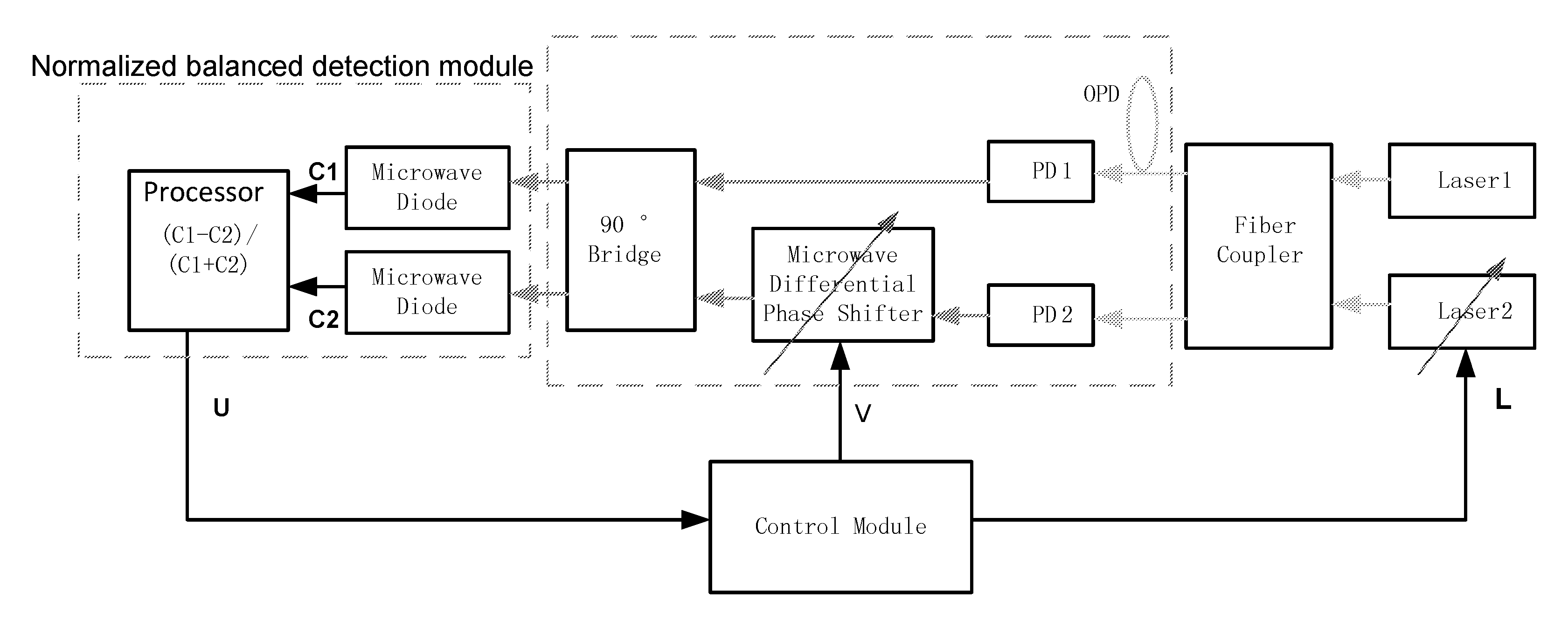
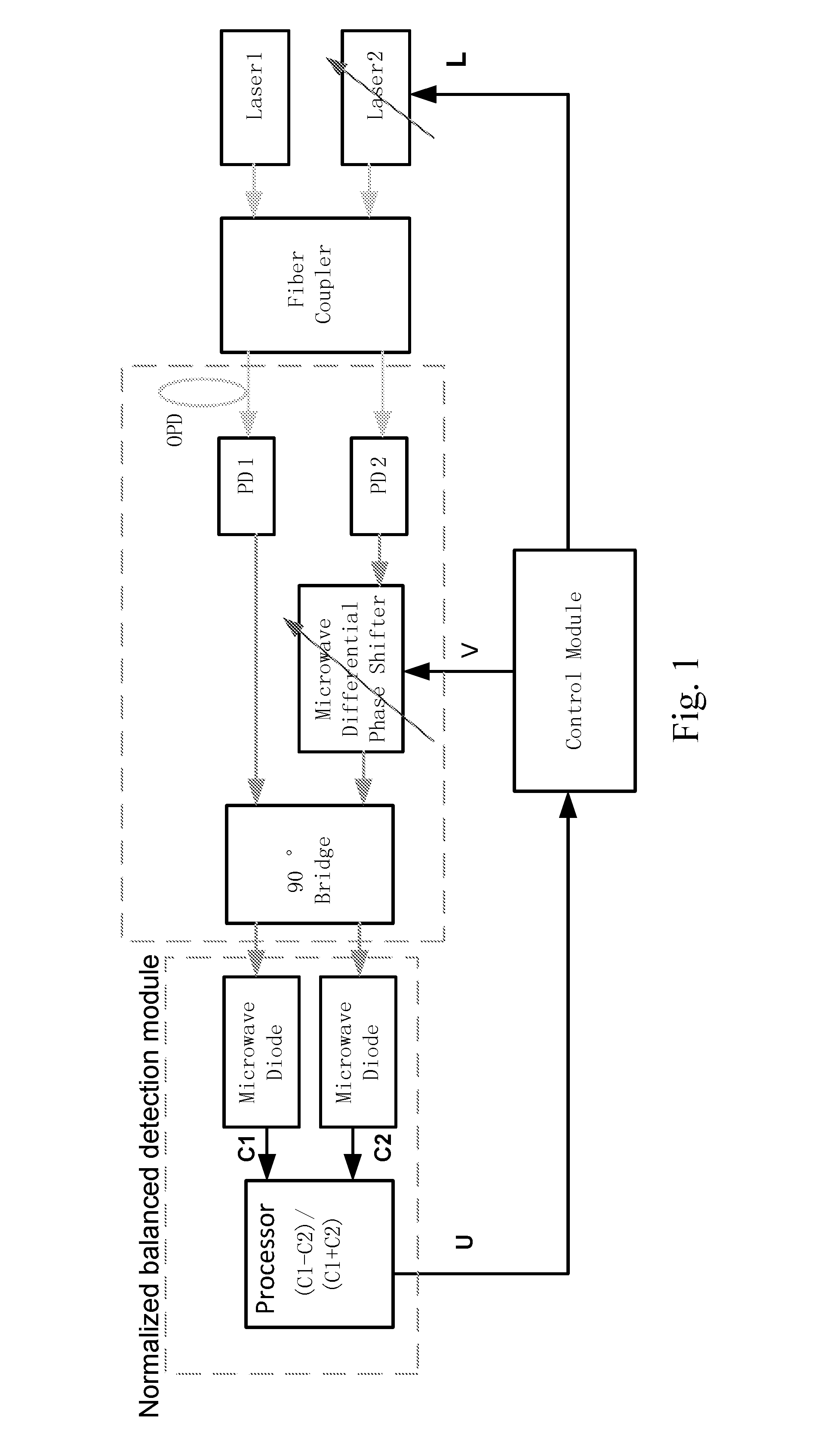
[0046]Referring to FIG. 1, a fiber coupler combines two lasers and outputs two identical channels of mixed light from two lasers. According to the present invention, two high-speed photodiodes PD1 and PD2 convert the mixed light to two channels of microwave signals. A frequency of the microwave signal fB is a frequency difference of the two lasers. After passing a microwave phase shifter in one arm, two channels are combined by a 90° microwave bridge. In fact, 90° microwave bridge is similar to a Mach-Zehnda optic-microwave interferometer. Two output channels from the 90° microwave bridge are similar to two outputs of the interferometer. The phase difference between two channels is given by:

Φ(V):=2·π·OPDc·fB+θ(V)

[0047]wherein θ(V) is the phase shift introduced by the microwave phase shifter, OPD is an optical path difference between the first light signal and the second light signal, fB is a frequency diff...


PUM


Abstract

An optic-microwave frequency discriminator includes: a fiber coupler receives and combines a first laser and a second laser, than the fiber coupler respectively generates and outputs a first light signal and a second light signal; a photodiode module respectively receives the first light signal and the second light signal, and converts the first light signal into a first microwave signal and converts the second light signal into a second microwave signal; a microwave phase shifter generates a shifted microwave signal by introducing a phase shift to the second microwave signal; a 90° microwave bridge combines the first microwave signal and the shifted microwave signal for generating a first bridge signal and a second bridge signal; a normalized balanced detection module generates an error signal; and a control module generates a controlling voltage signal according to the error signal for tuning a frequency of the second laser.

Description

CROSS REFERENCE OF RELATED APPLICATION[0001]The present invention claim claims priority under 35 U.S.C. 119(a-d) to CN 201610218562.2, filed Apr. 8, 2016.BACKGROUND OF THE PRESENT INVENTION[0002]1. Field of Invention[0003]The present invention relates to frequency difference locking techniques, and more particularly to an optic-microwave frequency discriminator for laser frequency difference locking, and a method thereof.[0004]2. Description of Related Arts[0005]Precise frequency difference locking between two lasers are required in variety of applications such as distributed temperature / strain sensing based on Brilliouin scattering, photonic generation of high microwave frequencies. Recent years, DFB lasers with extreme narrow line width (a few KHz) are commercially available. However, the frequency difference between two independent free-running lasers are changing all the time and drifting in a range of a few ten MHz. The present invention is about a novel frequency difference lo...

Claims


Application Information

Patent Timeline
Patent Type & Authority Applications(United States)
IPC IPC(8): H01S3/13H01S3/00H01S3/10H01S3/23
CPCH01S3/1304H01S3/2383H01S3/0092H01S3/1305H01S3/10092H01S3/10053H01S3/0014H01S3/0057H01S5/0687
Inventor WU, SHUDONGWANG, WENBO
Owner ZIBO QI RED PHOTOELECTRICAL TECH CO LTD
Why Eureka
Try Eureka