
Method and apparatus for detecting leaks in heat exchangers for motor vehicles

a technology for leak detection and heat exchangers, applied in lighting and heating apparatus, structural/machine measurement, instruments, etc., can solve the problems of wasting time, wasting helium, and wasting helium, so as to avoid the drawbacks of helium consumption, avoid the time of the machine, and avoid the effect of erroneous rejects

Inactive Publication Date: 2001-11-13
ALCATEL LUCENT SAS
View PDF15 Cites 36 Cited by
  • Summary
  • Abstract
  • Description
  • Claims
  • Application Information

AI Technical Summary

Benefits of technology

The problem posed by the present invention is to design a novel method and novel apparatus for leak-testing motor vehicle heat exchangers, with sensitivity that is as good as that of a conventional helium test, while avoiding the drawbacks of the cost of consuming helium, while avoiding the time the machine is out of action so as to be depolluted after being massively exposed to helium, and while avoiding erroneous rejects that can result from residual helium being detected.
Advantageously, to further improve the reliability with which leaks are detected, the leakproof test chamber prevents leakproofing of a quality that is significantly better than the quality of the leakproofing to be tested on a heat exchanger.
It is thus possible to use a pressurization device whose structure is particularly simple and of low cost.

Problems solved by technology

Parts that have been tested need subsequently to be dried, thereby lengthening the inspection cycle.
That method is of limited sensitivity.
Nevertheless, it suffers from various drawbacks.
That considerably increases the cost of the test.
Thereafter, after massive exposure to helium, it is necessary to leave the machine unoccupied for as long as it takes to enable it to be depolluted.
Also, the test is not entirely reliable since it often leads to acceptable parts being wrongly rejected.
What happens is that when a defective heat exchanger having leaks is tested, helium escapes into the test chamber.
After the defective heat exchanger has been withdrawn, residual helium can remain in the test chamber, thereby disturbing subsequent leak measurements on another heat exchanger, and giving the impression that said other heat exchanger also leaks.

Method used


Image

  • Method and apparatus for detecting leaks in heat exchangers for motor vehicles
  • Method and apparatus for detecting leaks in heat exchangers for motor vehicles

Examples


Embodiment Construction

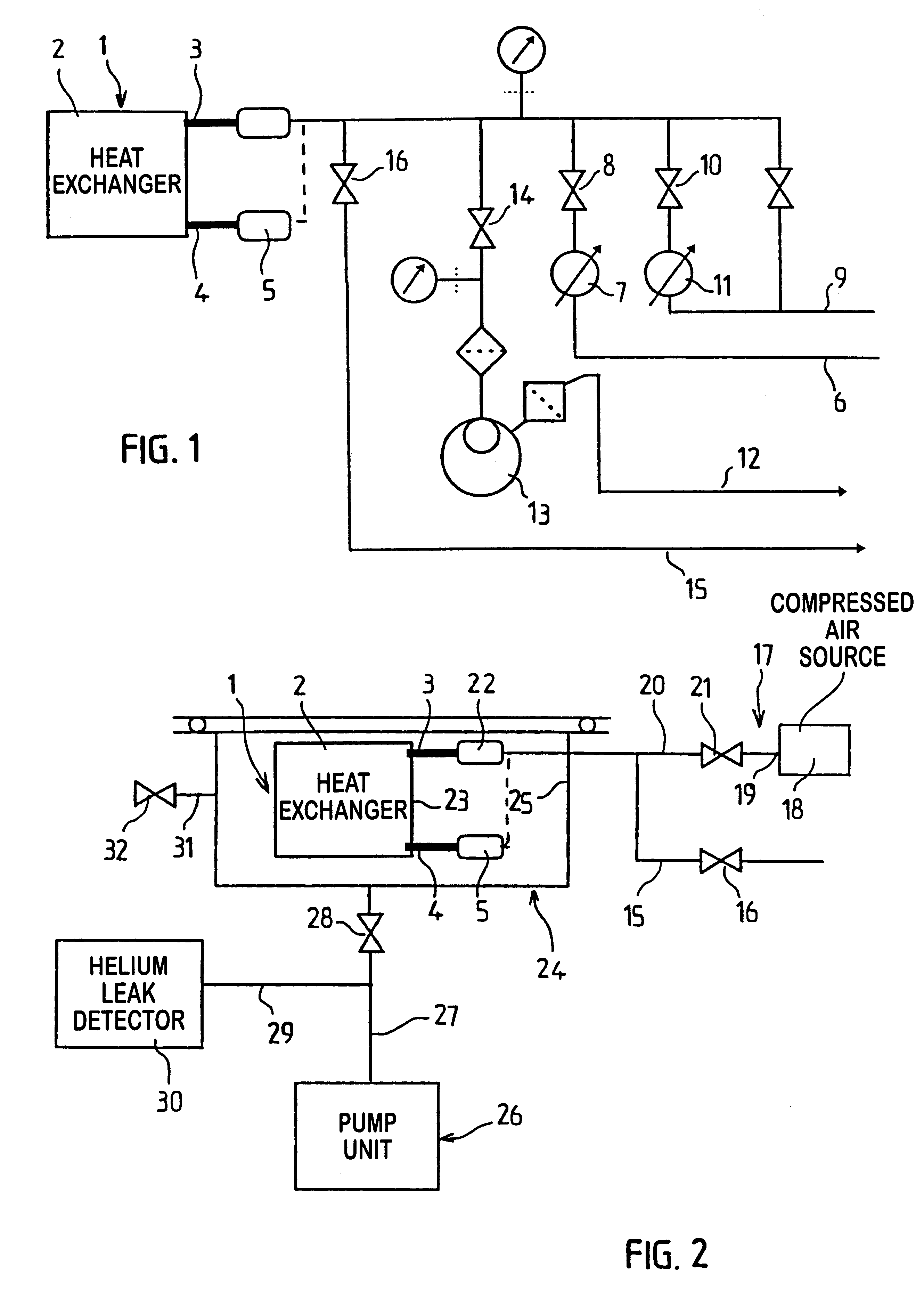
FIG. 1 is intended to show the relative complexity of a pressurization device as required for implementing a conventional helium test.

In such a test method, the heat exchanger 1 that has a leakproof internal cavity 2 conventionally includes an inlet pipe 3 and an outlet pipe 4. The outlet pipe 4 is closed with a stopper 5. Alternatively, the outlet pipe 4 can be connected to the inlet pipe 3 so as to increase gas flow and thus reduce test time. The inlet pipe 3 is connected to a set of pipes comprising:

an inlet pipe 6 for air under pressure, which pipe is provided with a pressure regulator 7 and a pressurized air inlet valve 8;

an inlet pipe 9 for helium under pressure which pipe is provided with at least one pressure regulator 11 and at least one pressurized helium inlet valve 10; and

an air exhaust pipe 12 provided with a primary pump 13 and with an air exhaust valve 14 to establish a vacuum of about 10 hPa, and an air or helium exhaust pipe 15 fitted with an exhaust valve 16.

All of...


PUM


Abstract

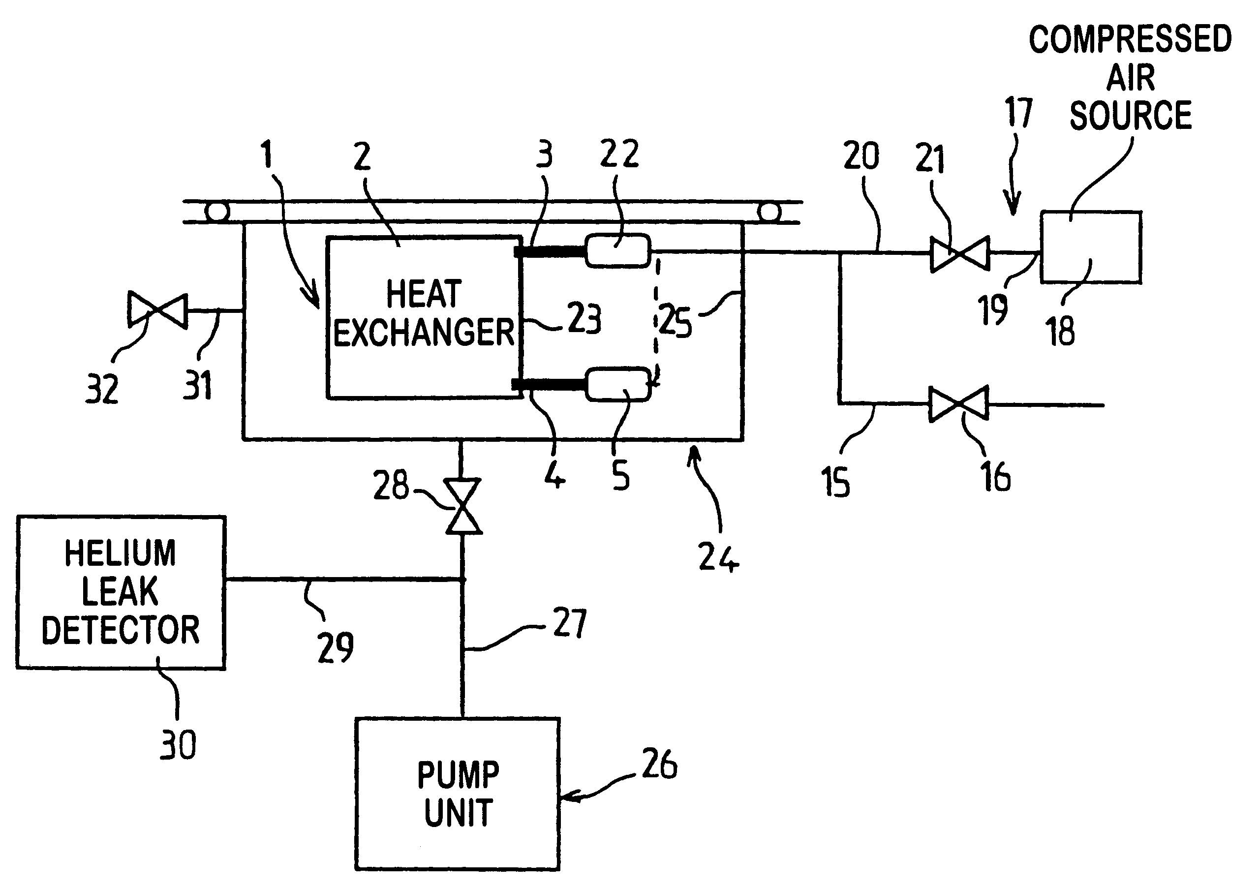
According to the invention, the presence of leaks is tested by placing the heat exchanger under test in a leakproof test chamber, by connecting the heat exchanger to a pressurization device that establishes an appropriate air pressure inside the internal cavity of the heat exchanger, by establishing a vacuum around the heat exchanger in the leakproof test chamber by means of a pump system, and by detecting the presence of helium around the heat exchanger in the leakproof test chamber by means of a helium leak detector. Testing is performed by using the helium which is naturally present in the air. This improves the availability of the machine and the reliability of the leak test, while also eliminating constraints and costs associated with using a tracer gas.

Description

The present invention relates to checking motor vehicle heat exchangers for leaks, for the purpose of enabling heat exchangers that have leaks greater than a predetermined threshold to be discarded.The invention can be applied to any motor vehicle heat exchanger, including radiators for cooling the engine, radiators for heating the vehicle cabin, air-air coolers for turbocharged engines, oil coolers, gasoline coolers, and in general any heat exchanger as used in a motor vehicle.At present, motor vehicle heat exchangers are leak-tested using various possible methods, which are selected as a function of the type of leak that is being looked for.A first method consists in immersing the heat exchanger in a liquid such as water, in putting the air in its internal cavity under pressure, and then looking for the appearance of bubbles leaving the heat exchanger and passing through the liquid. The quality of the results achieved depends significantly on the attention of the operator. Parts t...

Claims


Application Information

Patent Timeline
Patent Type & Authority Patents(United States)
IPC IPC(8): G01M3/22G01M3/20F28F27/00
CPCG01M3/228G01M3/229
Inventor SEIGEOT, BERTRAND
Owner ALCATEL LUCENT SAS
Learn More