Micro-geometry measuring device

a micro-geometry and measuring device technology, applied in the direction of mechanical measuring arrangements, mechanical roughness/irregularity measurements, instruments, etc., can solve the problems of micro-geometry on the workpiece surface being likely to be damaged, measuring force cannot be precisely controlled (stabilized) and excessive force causing bad influence on the surface of the workpi

Inactive Publication Date: 2001-11-13
MITUTOYO CORP
View PDF8 Cites 26 Cited by
  • Summary
  • Abstract
  • Description
  • Claims
  • Application Information

AI Technical Summary

Problems solved by technology

In other words, the measuring force differs according to a position of the stylus or a magnitude of irregularity of a workpiece, which causes error in detection result of surface position of the workpiece, and, when angle fluctuation is large, the measuring force can be so excessive as to effect bad influence on the surface of the workpiece.
On account of the indirect control, the measuring force cannot be controlled (stabilized) precisely enough for the stylus to accurately follow the irregularity on the surface of the workpiece.
However, micro-geometry on the workpiece surface is likely to be damaged by the stylus in the above arrangement.
Further, since the measuring force is controlled by the distal end of the lever arm, mechanical rigidity between the stylus and the distal end of the lever arm is small in the conventional example, so that responsivity thereof cannot be improved.
Accordingly, the measuring force working between the stylus and the workpiece is fifty microgram-force (.mu.gf) at the minimum, and measurement is difficult at a lower measuring force or with a faster arm movement.

Method used


Image

  • Micro-geometry measuring device
  • Micro-geometry measuring device
  • Micro-geometry measuring device

Examples


first embodiment

FIG. 1 to FIG. 4 show the present invention.

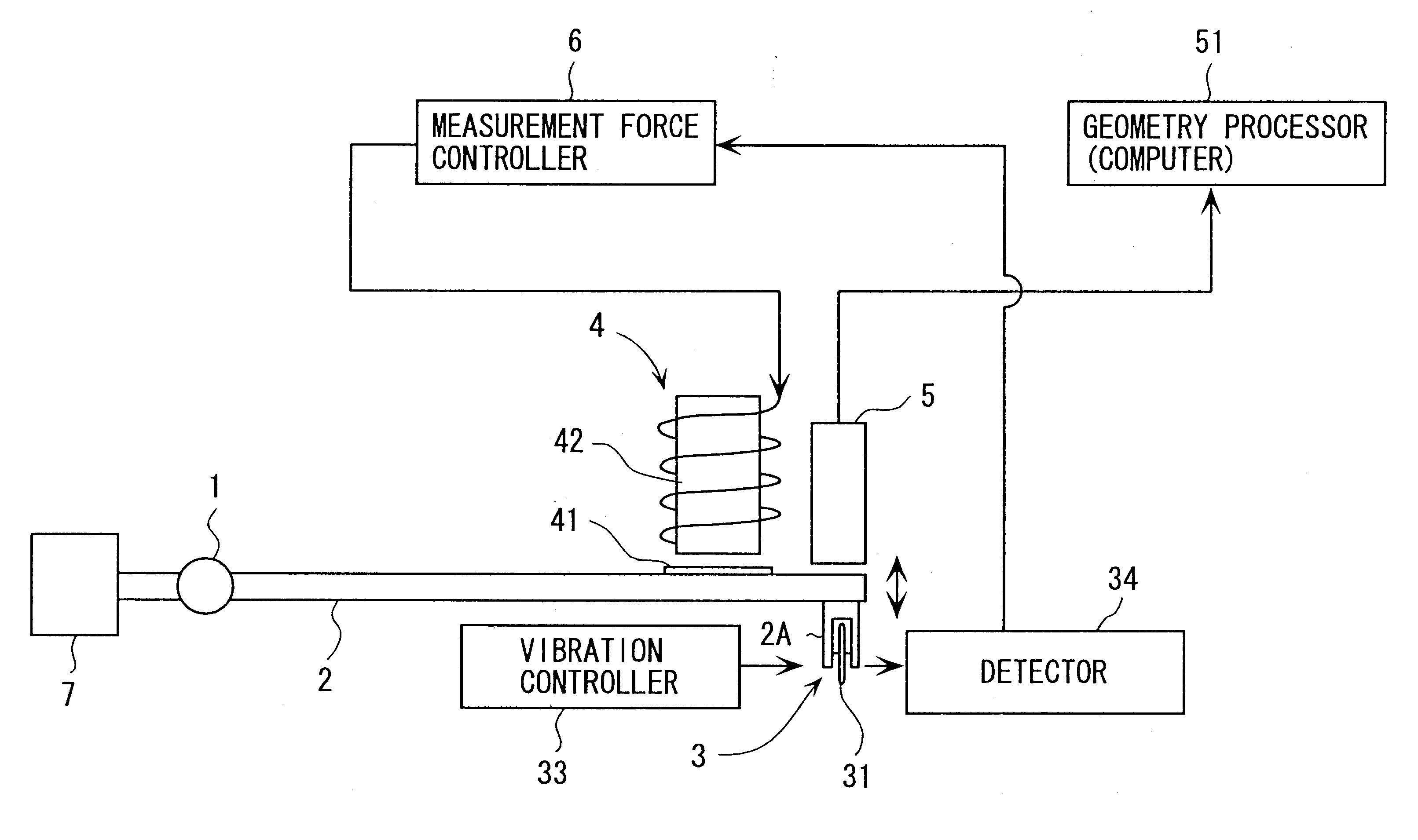
FIG. 1 is a summarized block diagram of a micro-geometry measuring device according to the first embodiment. In FIG. 1, the micro-geometry measuring device has an arm 2 pivotably provided to a frame (not shown) through a bearing 1, a stylus mechanism 3 provided to a lower surface of an end of the arm 2 through an attachment portion 2A of the arm 2 and having a stylus 31 to be in contact with a workpiece (not shown), a measuring force adjusting mechanism 4 for adjusting a measuring force working between the stylus 31 and the workpiece, a displacement sensor 5 for detecting a position of the arm 2, and a measuring force controller 6 for controlling the measuring force adjusting mechanism 4.

A balance weight 7 for balancing the weight of the stylus mechanism 3 around the bearing 1 is provided on the other end of the arm 2.

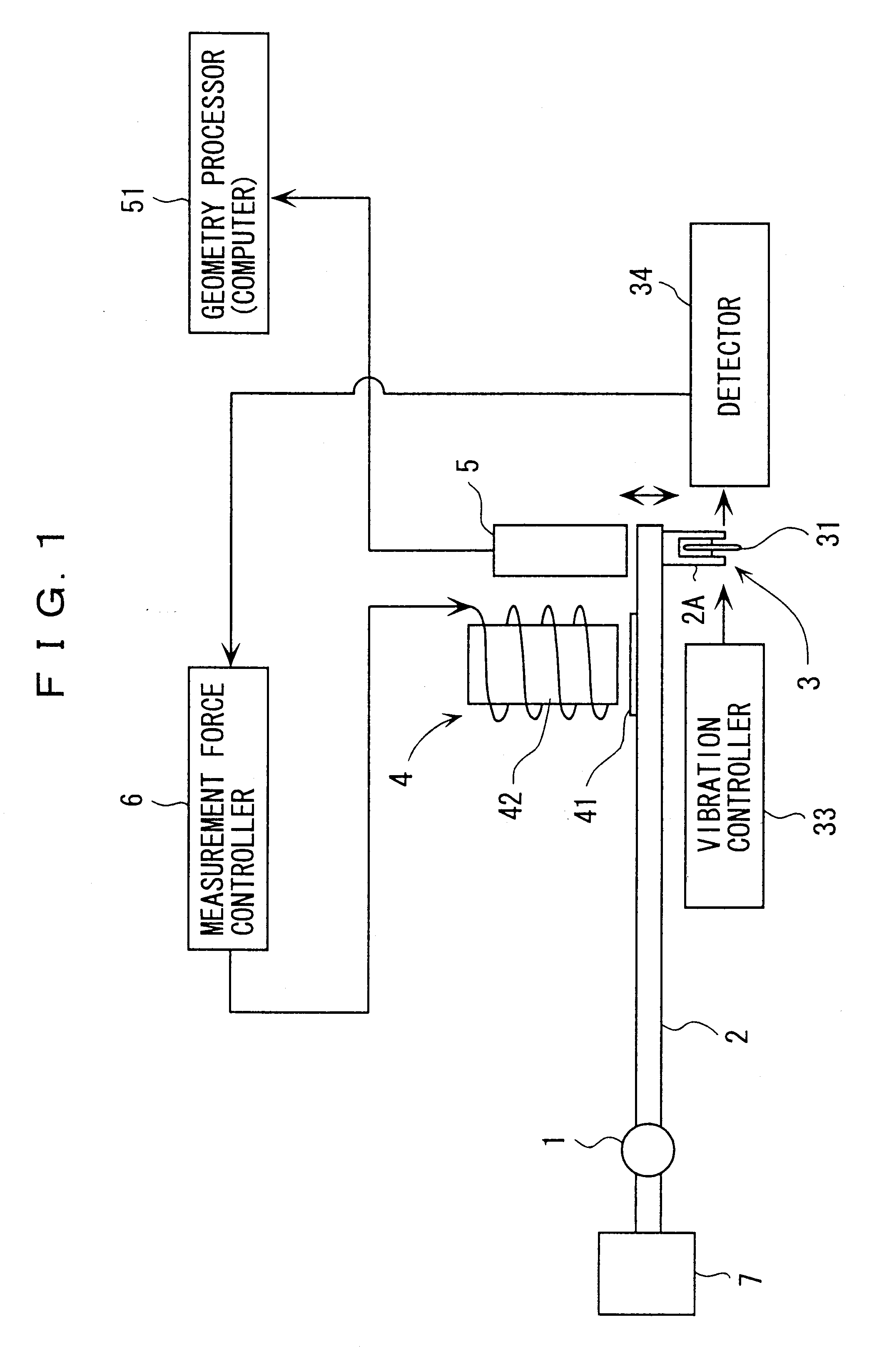
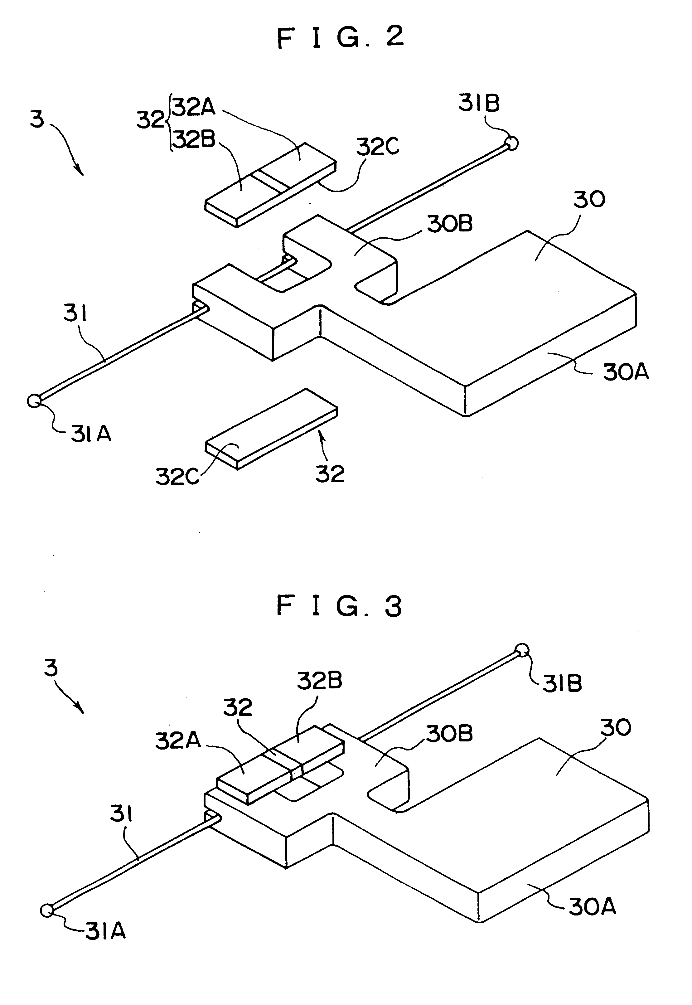
Detailed arrangement of the stylus mechanism 3 is shown in FIG. 2 and FIG. 3.

In the figures, the stylus mechanism 3 include...


PUM


Abstract

A micro-geometry measuring device capable of reducing measuring force thereof for avoiding damage on micro-geometry of workpiece surface and measuring at a high-speed is provided. The micro-geometry measuring device has a stylus mechanism having a stylus mechanism provided to an arm and having a stylus body, a measuring force adjusting mechanism for adjusting a measuring force working between the stylus body and the workpiece, a displacement sensor for detecting a position of the arm, and a measuring force controller for controlling the measuring force adjusting mechanism. The stylus mechanism includes a vibrator for resonantly vibrating the stylus body, and a detector for detecting vibration status changing when the stylus body touches the workpiece. The change in vibration of the stylus body vibrated by the vibrator is directly detected by the detector and a signal therefrom is fed back to the measuring force controller to keep constant measuring force working between the stylus body and the workpiece.

Description

1. Field of the InventionThe present invention relates to a micro-geometry measuring device for precisely measuring surface geometry of LSI, semiconductor wafers, or the like.2. Description of Related ArtSpecial devices are used for precisely measuring surface geometry of semiconductor wafers, etc. Published Japanese translation of PCT international publication for patent applications No. Hei 8-502357 and U.S. Pat. No. 5,309,755 are known as conventional examples of such device.The conventional example has an arm rotatably supported by a frame through a flexural pivot (elastic hinge), an end of the arm having a stylus made of a diamond tip and the other end of the arm having a movable plate.The movable vane (plate) moves between two parallel plates fixed to a base, the movable plate forming a bridge-electrode together with the parallel plates to be a pair of capacitor. When the arm pivotally moves, equilibrium of the bridge is lost and displacement of an end of the stylus is measure...

Claims


Application Information

Patent Timeline
Patent Type & Authority Patents(United States)
IPC IPC(8): G01B3/00G01B7/28G01B21/30
CPCG01B3/008G01B7/28
Inventor NISHIMURA, KUNITOSHI
Owner MITUTOYO CORP
Why Eureka
Try Eureka