Tactical missile control surface attachment

a technology of missile control and surface attachment, which is applied in the direction of self-propelled projectiles, weapons, projectiles, etc., can solve the problems of requiring special tools to attach the fin platform to the control shaft, and at best affecting the aerodynamic integrity of the aircraft,

Inactive Publication Date: 2001-11-13
RAYTHEON CO
View PDF10 Cites 11 Cited by
  • Summary
  • Abstract
  • Description
  • Claims
  • Application Information

AI Technical Summary

Problems solved by technology

A primary drawback to such an attachment assembly is the need for special tools to attach the fin platform to the control shaft.
It has also been found that maintaining the required tolerances between conventional tail fin assemblies and their missile attachment members can be difficult at best.
If the fastening screws attaching the tail fins to the missile are improperly torqued,

Method used


Image

  • Tactical missile control surface attachment
  • Tactical missile control surface attachment
  • Tactical missile control surface attachment

Examples


Embodiment Construction

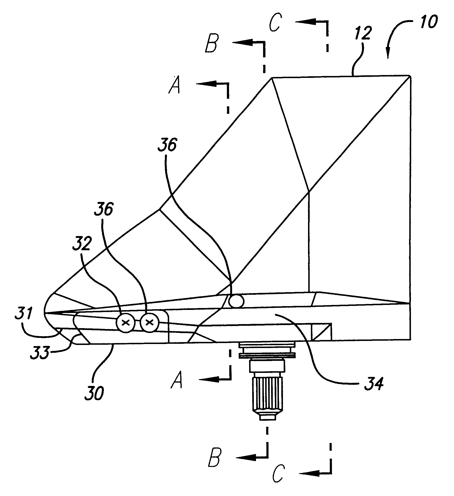
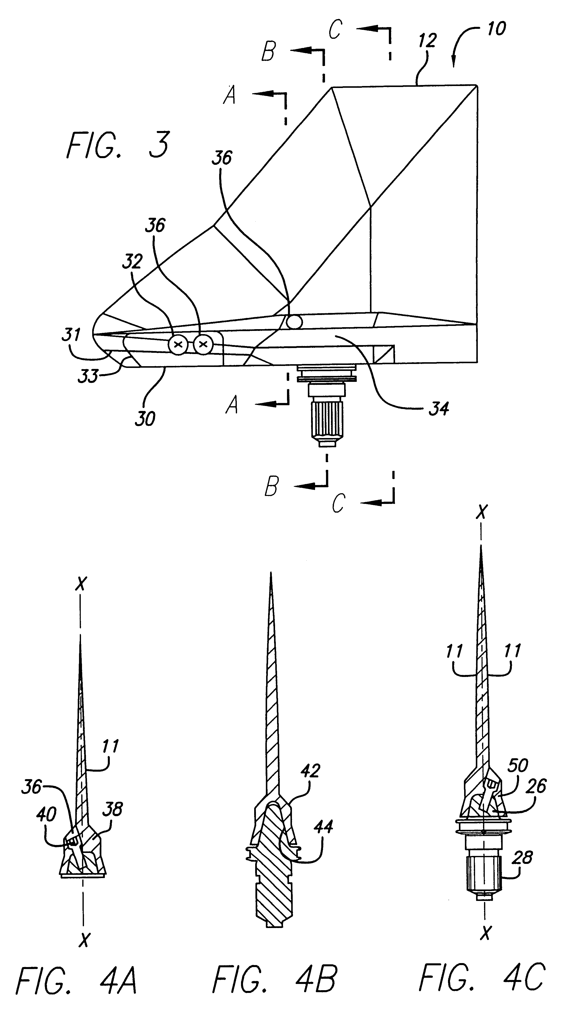
Illustrative embodiments and exemplary applications are described below with reference to the accompanying drawings in order to disclose the advantageous teachings of the present invention. As will be explained, the present invention is directed to a fin assembly having a unique design that allows it to be attached to a missile assembly without the need for special tooling. In addition, the mating surfaces of the fin and missile are configured to be press fit together with a pre-loaded pressure that can be readily controlled. As a result, the fin can be formed as a homogenous body rather than requiring honeycombing or the like to protect the fin.

Reference is now made to the accompanying drawings, wherein like reference numerals designate like elements throughout.

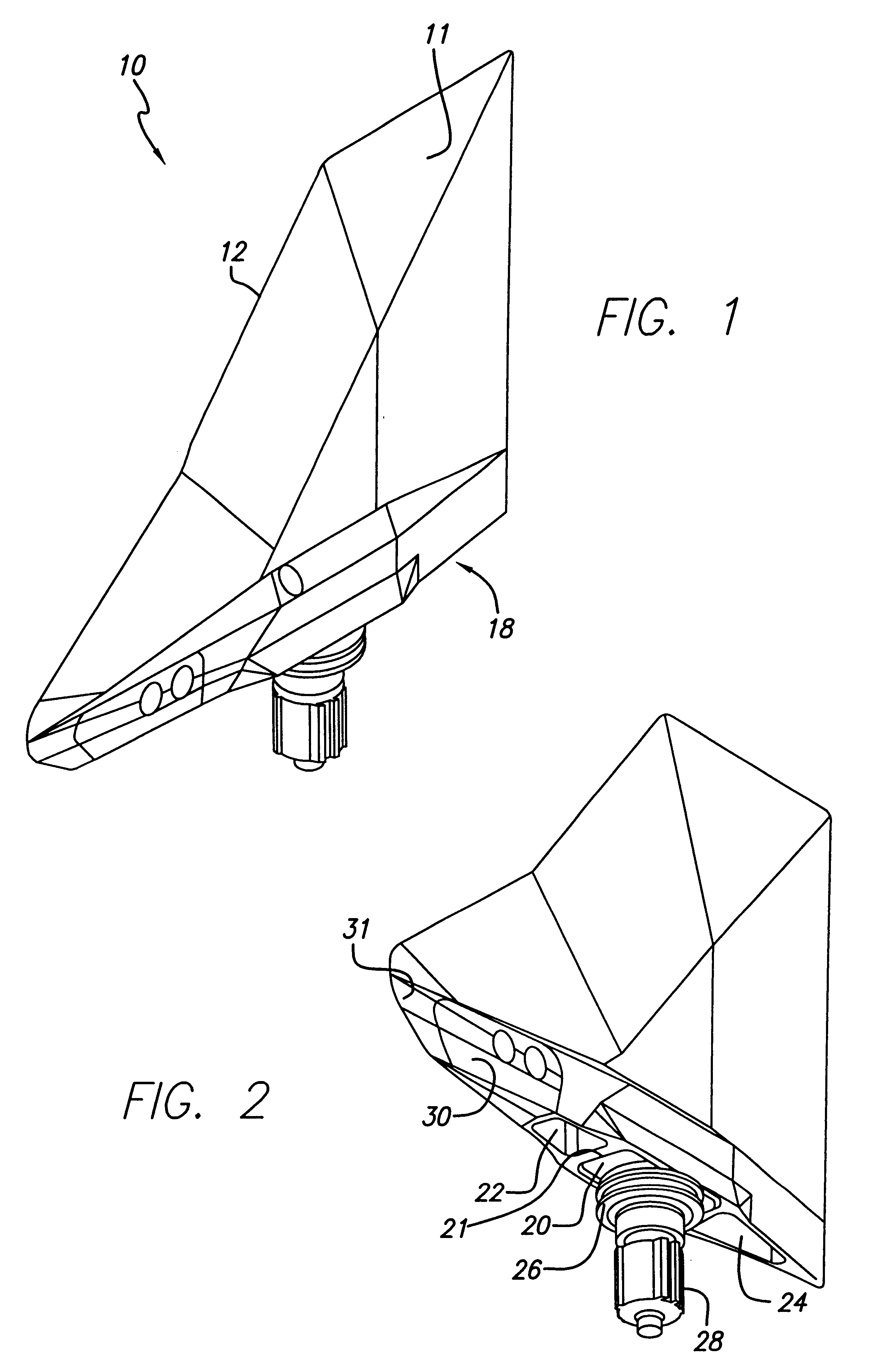
FIG. 1 is a perspective view of a tail fin assembly 10 formed in accordance with the present invention. Tail fin assembly 10 consists of pair of outer walls 11 joining each other to form an outer edge 12 having a double-delt...


PUM


Abstract

An improved tail fin assembly and method of attachment to a tactical missile capable of high performance motion. The tail fin is formed with a widened inner fin platform portion having a centrally disposed cavity formed by a pair of oppositely disposed walls inclined toward one another. An output control shaft extending from the missile includes a pair of oppositely disposed side walls inclined in a direction similar to the side walls of the cavity. When the tail fin is mounted on the output shaft, the end portion of the output shaft extends within the cavity until the side walls are confronting each other. A pair of fastening screws are advanced into aligned openings, drawing the inclined walls into surface contact to pre-load the tail fin assembly with preset tolerances.

Description

1. Field of the InventionThe present invention relates to an improved tail fin assembly and method of attachment as employed in a high performance tactical missile assembly2. Description of the Related ArtHigh performance tactical missiles employ a plurality of tail fins to control performance of the missile during flight to the target. Known missile assemblies mount each tail fin on a fin platform which is itself attached to the missile by special screws mounted on opposite sides of platform. In order to initiate movement of the tail fins, each platform is attached to a control shaft that mates to the bottom surface of the tail fin assembly. As the control shaft is made to rotate, the attached tail fin also rotates in a pre-determined direction, thereby controlling movement of the tactical missile assembly. A primary drawback to such an attachment assembly is the need for special tools to attach the fin platform to the control shaft. Such tools must be maintained in the inventory o...

Claims


Application Information

Patent Timeline
IPC IPC(8): F42B10/00F42B10/64
CPCF42B10/64
Inventor RASMUSSEN, PERRYBROGMUS, ERICSTUBBS, SCOTT
Owner RAYTHEON CO
Why Eureka
Try Eureka