Multi-purpose hydraulic press, metal bending, and log splitting apparatus

a multi-purpose, hydraulic press technology, applied in the direction of other manufacturing equipment/tools, wood splitting, manufacturing tools, etc., can solve the problems of deteriorating the functionality of a particular purpose tool, the inability to easily be modified into a more general purpose tool, and the deminimus pri

Inactive Publication Date: 2001-11-20
ELFRINK HERMAN F
View PDF15 Cites 16 Cited by
  • Summary
  • Abstract
  • Description
  • Claims
  • Application Information

AI Technical Summary

Benefits of technology

An advantage of the present invention is that it can provide all of the functionality of an otherwise conventional log splitter.
Another advantage of the present invention is that it can allow for application of hydraulic force within the throat area of the device for purposes other than splitting logs.
Yet another advantage of the present invention is that is can allow for transmission of hydraulic force to areas outside the throat area of the device.
Further, a preferred embodiment of the present invention can be made portable, adaptable, and as reasonably priced as conventionally available log splitter.
The advantages and features of the present invention will become better understood with reference to the following more detailed description and claims taken in conjunction with the accompanying drawings, in which like elements are identified with like symbols, and in which:

Problems solved by technology

In fact, most equipment rental facilities can provide such a tool for a limited time and for a very deminimus price.
The only problem occurs from the design of the log splitter is that it is, in fact, particularly well adapted for splitting logs, and cannot easily be modified into a more general purpose tool.
Any attempts that have been made to make the log splitter into a general purpose tool have inevitably resulted in deterioration of its functionality as a particular purpose tool.

Method used


Image

  • Multi-purpose hydraulic press, metal bending, and log splitting apparatus
  • Multi-purpose hydraulic press, metal bending, and log splitting apparatus
  • Multi-purpose hydraulic press, metal bending, and log splitting apparatus

Examples


Embodiment Construction

of the Figures

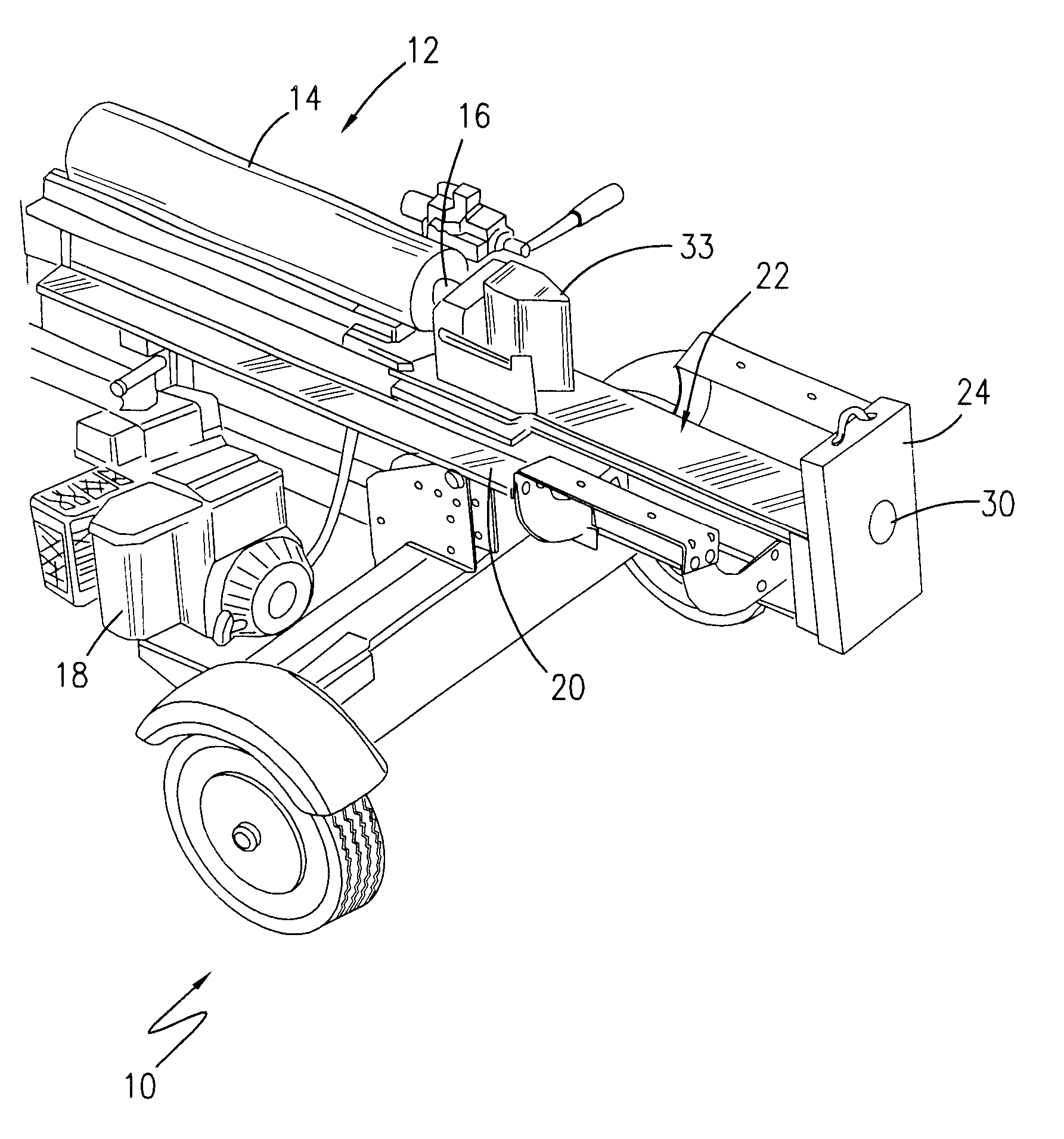
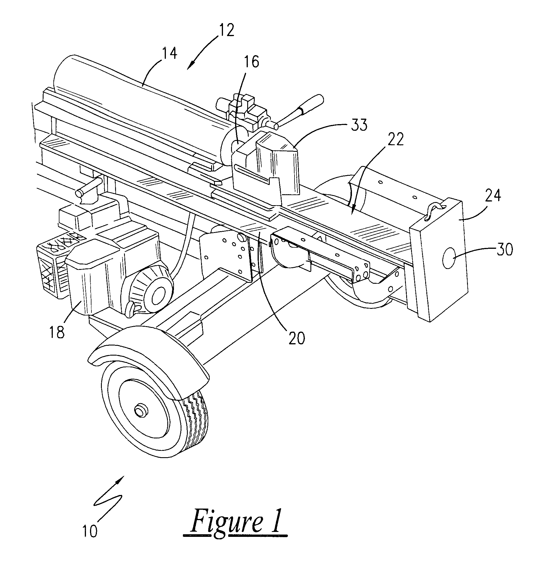
Referring now to FIG. 1, a perspective view of a multi-purpose hydraulic press, metal bending, and log splitting apparatus 10 is shown, according to the present invention. An hydraulic ram 12, having a piston cylinder 14 for extending and retracting a piston rod 16 driven by an hydraulic power means 18, is rigidly affixed to an elongated I-beam frame member 20, the central portion of which spans a throat area 22 bounded on one side by the hydraulic ram 12 and on the opposite side by a rigidly attached foot plate 24. The foot plate 24 is formed of a planar steel member affixed perpendicularly to the frame member 20, and forms a ram extension penetration orifice 30 within the plane of the plate 24 in a position aligned with the piston rod 16.

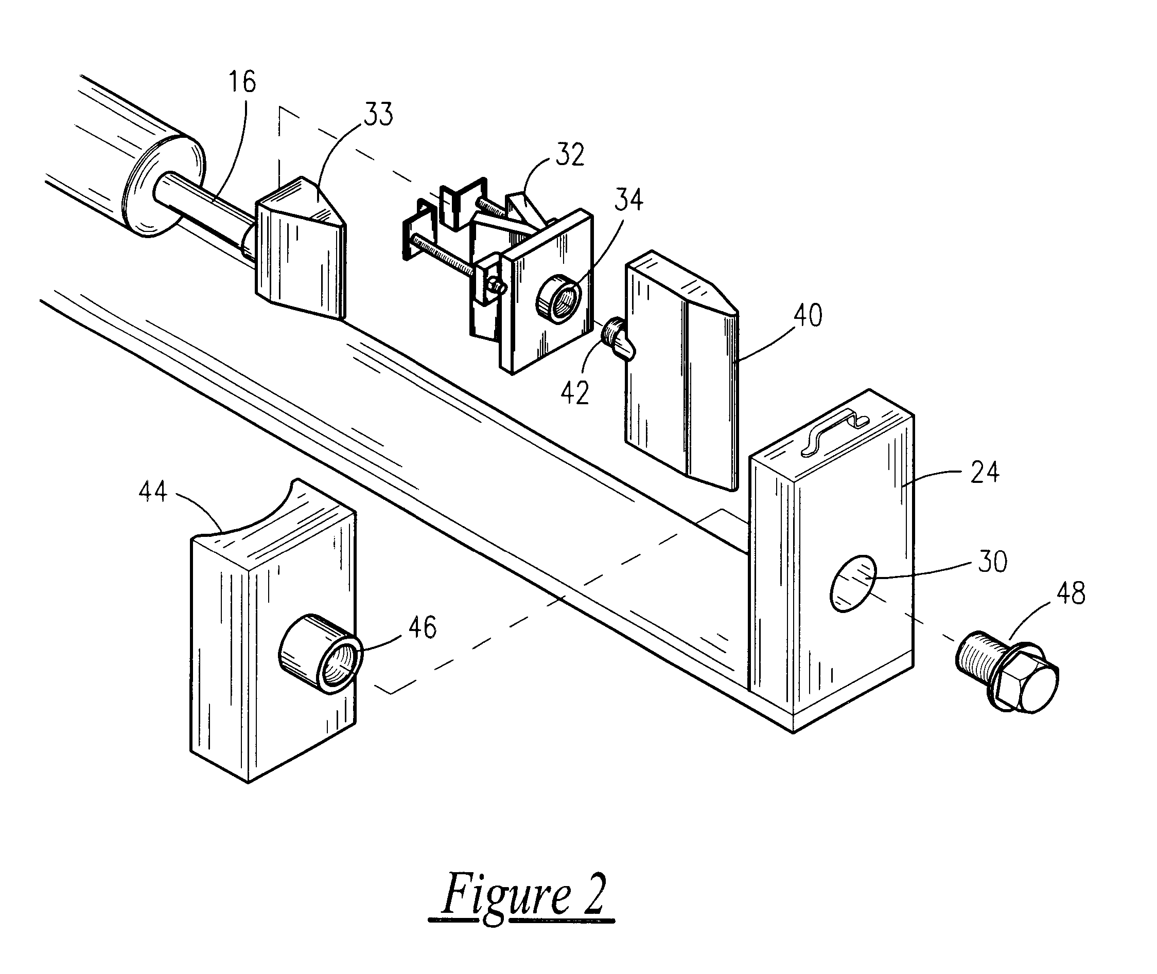
In conjunction with FIG. 2, a series of functional inserts are included for placement against the foot plate or piston rod. Particularly, an attachment saddle 32 is shown in conjunction with FIG. 3, as being mounted to the wedge 33 o...


PUM

PropertyMeasurementUnit
areaaaaaaaaaaa
lengthaaaaaaaaaa
hydraulic forceaaaaaaaaaa

Abstract

A multi-purpose hydraulic press, metal bending, and log splitting apparatus is disclosed. An hydraulic ram, having a piston cylinder for extending and retracting a piston rod driven by an hydraulic power means, is rigidly affixed to an elongated I-beam frame member, the central portion of which spans a throat area bounded on one side by the hydraulic ram and on the opposite side by a rigidly attached foot plate. The foot plate is formed of a planar steel member affixed perpendicularly to the frame member, and forms a ram extension penetration orifice within the plane of the plate in a position aligned with the piston rod. A series of functional inserts are included for placement against the foot plate or piston rod. A series of functional extension elements are also included for placement against the piston rod for extension through the ram extension penetration orifice. These functional extensions thereby allow the apparatus to be adapted to transmit its hydraulic ram capacity outward, in a controllable fashion, past the working throat of the apparatus.

Description

There are no previously filed, nor currently any co-pending applications, anywhere in the world.1. Field of the InventionThe present invention relates generally to log splitting apparatus and, more particularly, to methods of adapting an otherwise conventional log splitter for purposes of multiple, extending applications.2. Description of the Related ArtAs is well-known in the art, hydraulic log splitters are well know and widely available. They are reliable, well made, provide a great capacity of hydraulic force, can be made portable, and, due to their popularity, are reasonable in price and availability. In fact, most equipment rental facilities can provide such a tool for a limited time and for a very deminimus price. Although many different brands are available, each with minor modifications relative to one another, all have some similar basic functional features. For example, a hydraulic power means has been shown to be an effective source of power for purposes of splitting log...

Claims


Application Information

Patent Timeline
Patent Type & Authority Patents(United States)
IPC IPC(8): B21D9/08B21D5/02B21D9/00B27L7/00
CPCB21D5/02B27L7/00B21D9/08Y10T29/50Y10T83/9437
Inventor ELFRINK, HERMAN F.
Owner ELFRINK HERMAN F
Why Eureka
Try Eureka