
Flexible conductive tape connection

a technology of conductive tape and flexible conductor, which is applied in the direction of cable, coupling device connection, laminated bus-bar, etc., can solve the problems of strip conductor breakage and possible shock

Inactive Publication Date: 2001-11-20
ROBERT BOSCH GMBH
View PDF14 Cites 14 Cited by
  • Summary
  • Abstract
  • Description
  • Claims
  • Application Information

AI Technical Summary

Benefits of technology

In the further development with the characterizing features of claim 1, the flexible strip conductor connections of the type described at the outset is advantageous in that a buffer for the mechanical shocks is created by the loop in the flexible foil, or respectively in the strip conductors. A change in the length of the foil and the strip conductors of a size between 0 and 300 .mu.m is caused by the shocks transmitted to the flexible foil. The installation of the loops in accordance with the invention here results in a reduction of the expansions caused by the shocks and of the mechanical stress in the strip conductors and the flexible foil.This reduction in the stretching of the strip conductors in the course of the individual shocks, which is also successfully provided in the further developments in the dependent claims, increases the long-time service life of the strip conductors, so that the loss of the sensors as an external component because of a break in the strip conductors in the flexible foil is prevented to a large extent during the length of operation of the arrangement.

Problems solved by technology

For example, if the angle sensor is employed on the pump shaft of a fuel injection pump of a motor vehicle, there is the possibility of shocks, which are a function of the number of cylinders in particular, being transmitted to the flexible foil.
These relatively frequent and short shocks can lead to breakage of the strip conductors in the foil, mainly at the clamping location of the flexible foil between the cover and the housing of the angle sensor, and therefore to error functions.

Method used


Image

  • Flexible conductive tape connection
  • Flexible conductive tape connection
  • Flexible conductive tape connection

Examples


Embodiment Construction

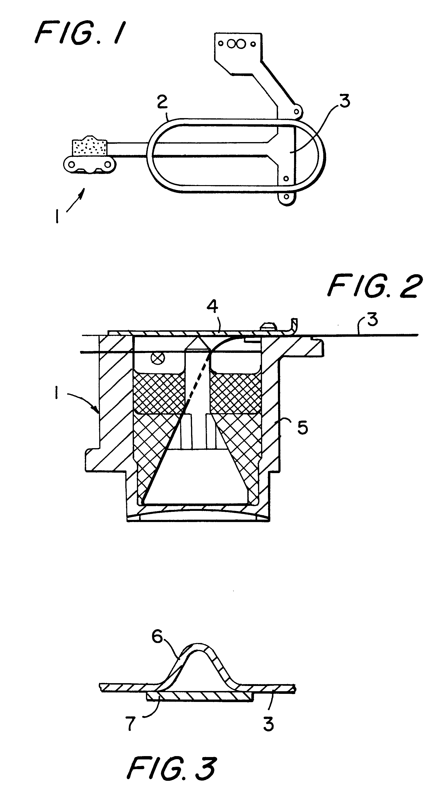
The housing of an angle of rotation sensor 1, portions of a control device 2 and a flexible strip conductor connection 3 are represented in FIG. 1 of the drawings. The angle of rotation sensor is used to detect the angle of rotation of a driveshaft for controlling a fuel injection pump of a motor vehicle, not represented here.

From the sectional representation in FIG. 2 it can be seen that the flexible strip conductor foil 3 is clamped between a cover 4 and a housing 5. The actual angle of rotation encoder, not explained in detail here, in the housing 5 is situated in the area of the fuel injection pump arrangement, and therefore the housing is subjected to the mechanical vibrations of the fuel pump.

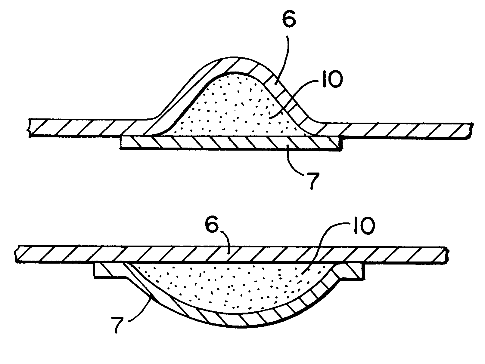
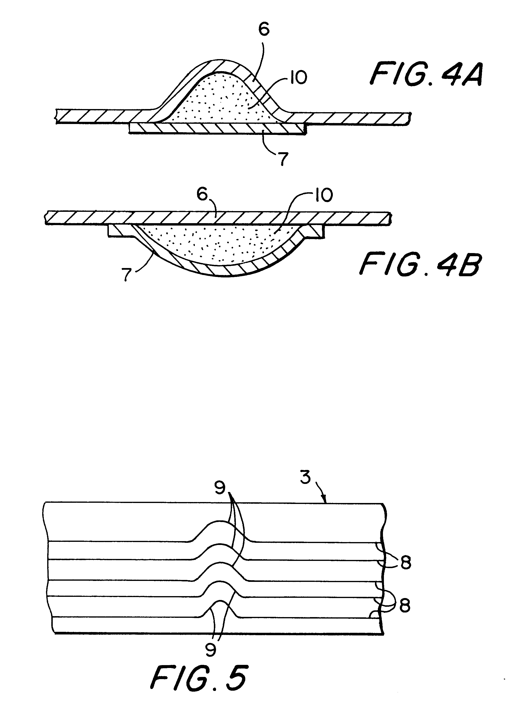
An exemplary embodiment of the invention in accordance with FIG. 3 has a buffer in the form of a loop 6 in the course of the flexible strip conductor foil in order to reduce the stretching of the strip conductors in the flexible foil 3 during the shock movements of the fuel pump. The loop...


PUM

PropertyMeasurementUnit
widthaaaaaaaaaa
sizeaaaaaaaaaa
sizeaaaaaaaaaa

Abstract

The invention relates to a flexible strip conductor connection, by means of which electrical connections between an electrical device (2) and an external component (1) can be made, wherein the strip conductors (8) are located in or on a flexible foil (3), which is clamped on the electrical device (2) as well as the external component (1). In a predetermined area in the course of the strip conductors (8), the flexible foil (3) has a loop (6), which can be filled with an elastic material perpendicularly in relation to the foil plane, or the strip conductors (8) in the plane of the foil respectively have a loop-shaped deviation (9) perpendicularly to the course of strip conductor.

Description

PRIOR ARTThe invention relates to a flexible strip conductor connection, in particular for a control or regulating device having a set-off sensor or servo component, in accordance with the preamble of claim 1.In a flexible strip conductor connection known from DE 40 38 394 A1, an electrical connection is provided between a control arrangement for a magnetic valve in a motor vehicle and an angle sensor for detecting the angle of rotation of a fuel injection pump. The angle sensor is supplied with an electrical voltage by means of the strip conductors placed into a flexible foil and emits a sensor signal to the control device.With the known angle sensor, the flexible foil is clamped between the cover and the housing so that when the unit, on which the angle sensor is fastened, is operated, mechanical vibrations are transmitted to the flexible foil. For example, if the angle sensor is employed on the pump shaft of a fuel injection pump of a motor vehicle, there is the possibility of sh...

Claims


Application Information

Patent Timeline
Patent Type & Authority Patents(United States)
IPC IPC(8): H02G5/00H05K1/00H05K1/02H01B3/30H01R12/24H01B5/14H01R12/08H01R13/66H02B1/20H02G15/007
CPCH02G5/005H05K1/028H05K1/0281H05K1/0283H05K1/0271H05K2201/0133H05K2201/09109H05K2201/09281H05K2201/2009H01R13/66
Inventor MOESSINGER, JUERGENGROTE, WALTER
Owner ROBERT BOSCH GMBH
Learn More