Turbocharger system to inhibit surge in a multi-stage compressor

a multi-stage compressor and turbocharger technology, applied in the direction of machines/engines, rotary clutches, fluid couplings, etc., can solve the problems of no further flow rate increase, interruption of discharge process,

Inactive Publication Date: 2001-12-04
CATERPILLAR INC
View PDF14 Cites 60 Cited by
  • Summary
  • Abstract
  • Description
  • Claims
  • Application Information

AI Technical Summary

Problems solved by technology

With too small a volume flow and too high a pressure ratio, the flow will separate from the suction side of the blades on the compressor wheel, with the result that the disch

Method used


Image

  • Turbocharger system to inhibit surge in a multi-stage compressor
  • Turbocharger system to inhibit surge in a multi-stage compressor

Examples


Embodiment Construction

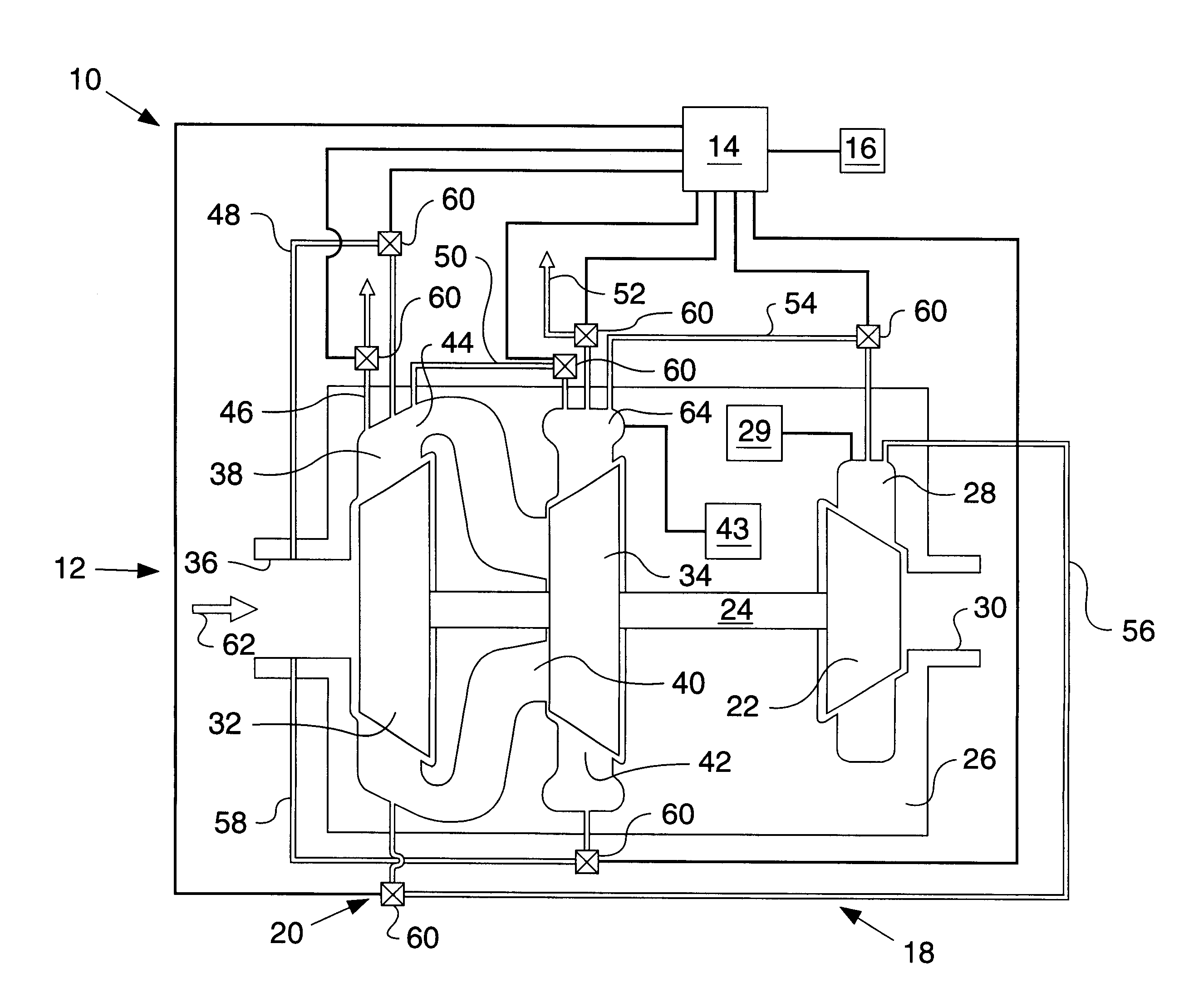
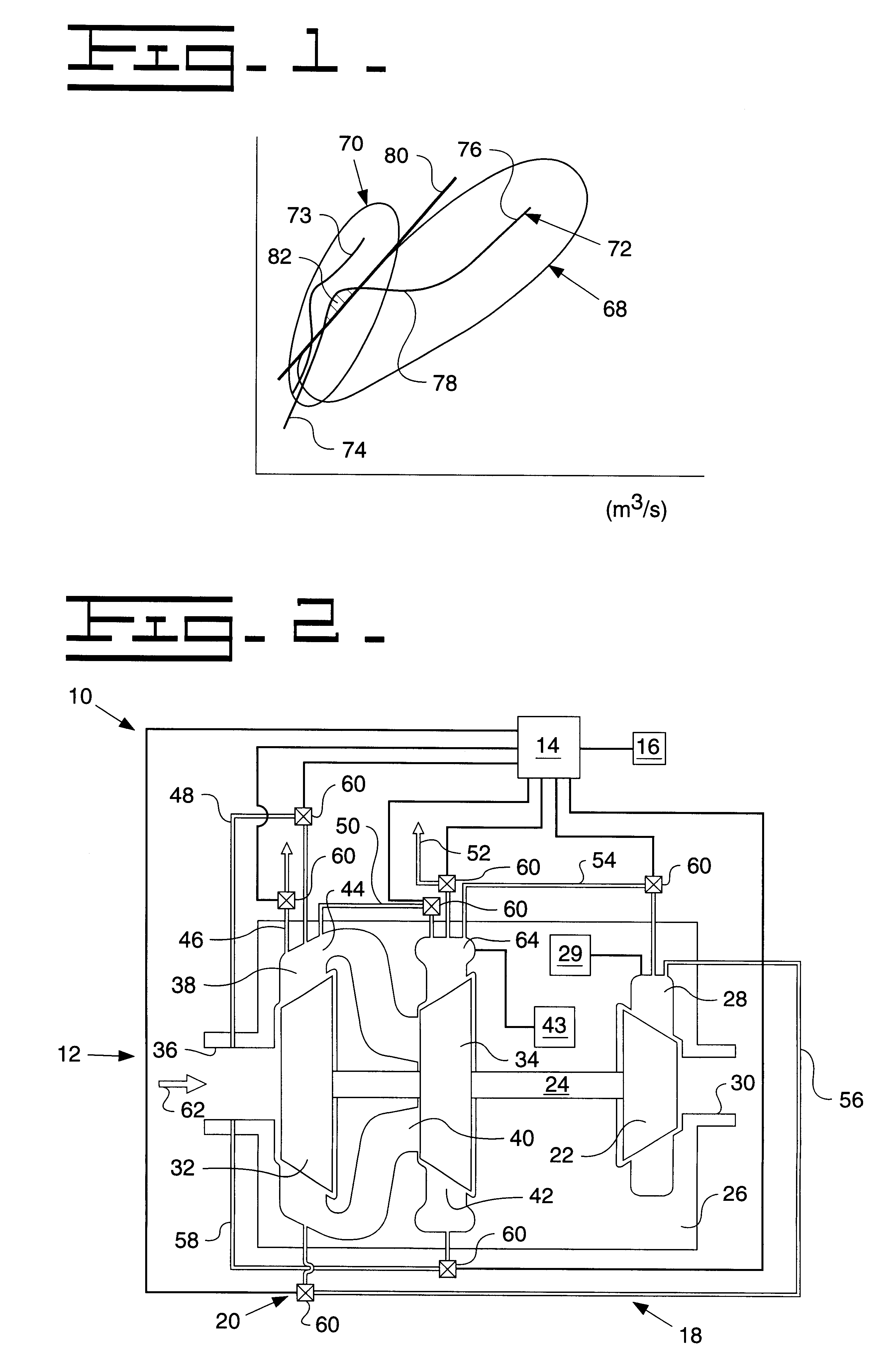
Referring now to the drawings, and more particular to FIG. 1, there is shown an operating map for a multi-stage (i.e., two-stage) compressor 20 of turbocharger 12 shown in FIG. 2 and described in more detail hereinafter. Map 68 represents the operating behavior of first compressor wheel 32, and map 70 represents the operating behavior of second compressor wheel 34. Together, maps 68 and 70 combined with the engine air flow / pressure ratio characteristics define an operating curve 72 for the low pressure stage and 73 for the second stage of two-stage compressor 20.

In general, as the volumetric flow rate of turbocharger 12 increases as a result of increased shaft speed, the pressure ratio of turbocharger 12 likewise increases. A lower portion 74 of operating curve 72 corresponds to engine low speed conditions, and upper portion 76 corresponds to engine high speed conditions, and an intermediate portion 78 corresponds to a transition zone on operating curve 72 where the operating curve ...


PUM


Abstract

A turbocharger system for an internal combustion engine is provided with at least one rotatable shaft and a multi-stage compressor. The multi-stage compressor includes a first compressor wheel carried by a corresponding shaft, an axially extending first inlet associated with the first compressor wheel, a radially extending first outlet associated with the first compressor wheel, a second compressor wheel carried by a corresponding shaft, an axially extending second inlet associated with the second compressor wheel, and a radially extending second outlet associated with the second compressor wheel. An interstage duct fluidly interconnects in series the first outlet associated with the first compressor wheel with the second inlet associated with the second compressor wheel. At least one bypass duct is provided, with each bypass duct fluidly interconnecting the first outlet with the first inlet; the first outlet with an ambient environment; and/or the second outlet with the first outlet. At least one valve is provided, each valve being positioned within a corresponding bypass duct. A controller is coupled with each valve and selectively actuates each valve.

Description

TECHNICAL FIELDThe present invention relates to a turbocharger for use in an internal combustion engine, and, more particularly, to a turbocharger including a multi-stage compressor.BACKGROUND ARTAn internal combustion engine may include one or more turbochargers for compressing a fluid which is supplied to one or more combustion chambers within corresponding combustion cylinders. Each turbocharger typically includes a turbine driven by exhaust gases of the engine and a compressor which is driven by the turbine. The compressor receives the fluid to be compressed and supplies the fluid to the combustion chambers. The fluid which is compressed by the compressor may be in the form of combustion air or a fuel and air mixture.The operating behavior of a compressor within a turbocharger may be graphically illustrated by a "compressor map" associated with the turbocharger in which the pressure ratio (compression outlet pressure divided by the inlet pressure) is plotted on the vertical axes...

Claims


Application Information

Patent Timeline
IPC IPC(8): F02B37/013F02B37/12F02B37/16
CPCF02B37/013F02B37/16F02B37/164Y02T10/144Y02T10/12
Inventor GLADDEN, JOHN R.WU, MIN
Owner CATERPILLAR INC
Why Eureka
Try Eureka