Coat transfer tool

a transfer tool and coating technology, applied in the field of coating transfer tools, can solve the problems of difficult manufacturing of coating strips, limited displacement of coating strips, and elastic displacement subject to inevitable limits

Inactive Publication Date: 2001-12-04
KOTOBUKI & CO LTD
View PDF3 Cites 15 Cited by
  • Summary
  • Abstract
  • Description
  • Claims
  • Application Information

AI Technical Summary

Benefits of technology

As the elastic pressing body provides a sufficient elastic force to the applying strip, the force that the applying strip receives from the surface of the substrate is buffered and, simultaneously when a coat layer of the tape is to be transferred and when the coat layer of the tape is to be cut, the applying strip can be placed at respective, appropriate angles relative to the surface of the substrate. Therefore, when transferring is to be continued, the coat layer is reliably supplied from the transferring tool to the surface of the substrate without being unintentionally cut and, when transferring is to be completed, the coat layer can be neatly cut.
According to a third aspect of the invention, the plate-shaped part of the case integrated with the elastic pressing body, as in the second aspect of the invention, has a side window where it overlaps with the elastic pressing body as viewed in a direction substantially orthogonal to the plate-shaped part. As the side window is formed, the elastic pressing body can be readily formed with the case.

Problems solved by technology

However, as the conventional coat transfer tool causes the applying strip to be deformed by its own elasticity, a problem results in that its elastic displacement is subject to an inevitable limit and the applying strip is difficult to manufacture.
As the movement of the elastic pressing body is limited by the limiting unit, the displacement of the applying strip can also be limited.

Method used


Image

  • Coat transfer tool
  • Coat transfer tool
  • Coat transfer tool

Examples


first embodiment

Referring to FIGS. 1-8, there is illustrated a coat transfer tool according to a first embodiment of the present invention. A coat transfer tape which is employed in the coat transfer tool can be conventional having a coat of composition coating one side of a plastic carrier film through a peeling layer, and a layer of adhesive, such as pressure sensitive adhesive, coating the coat of composition.

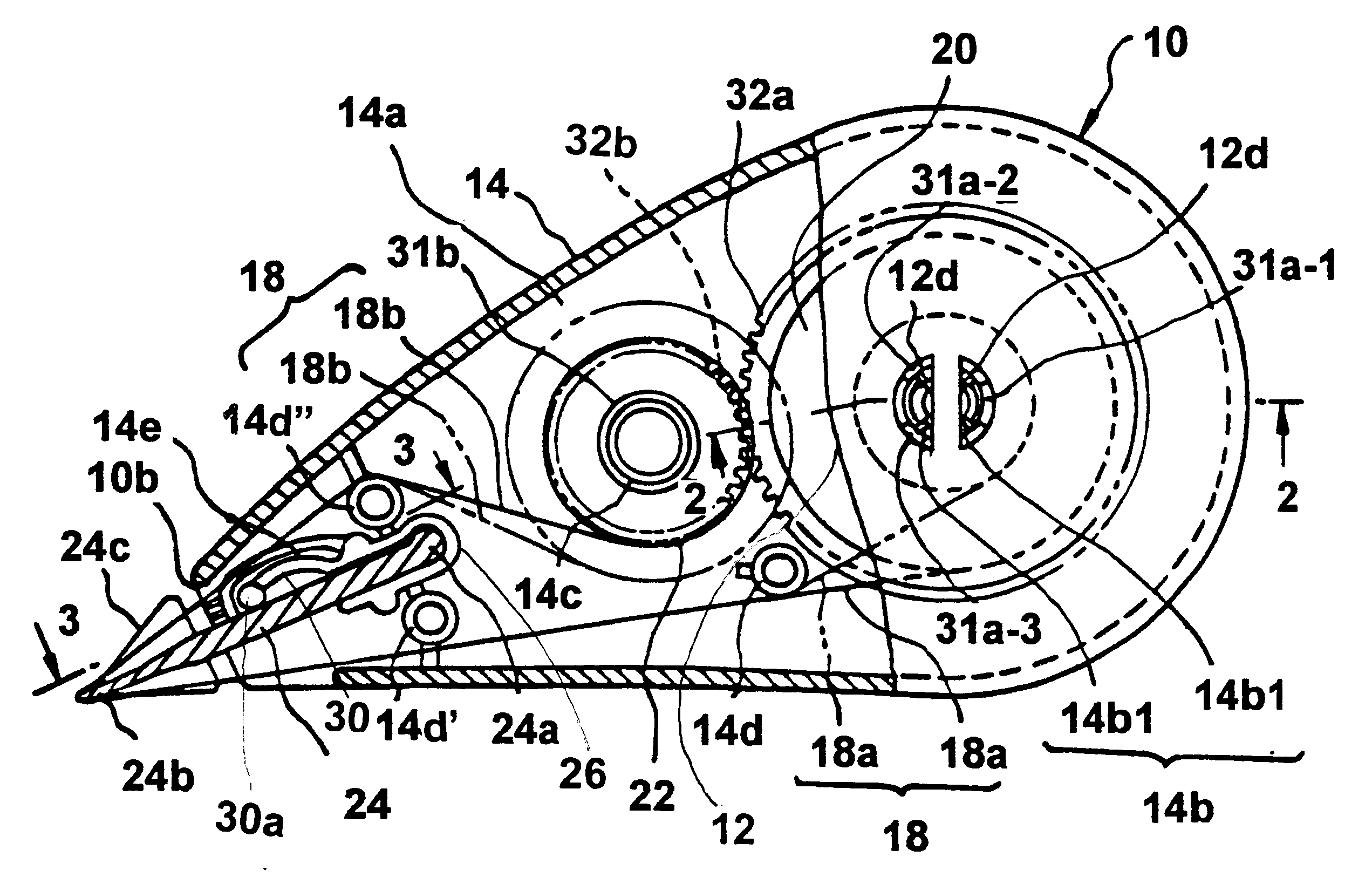
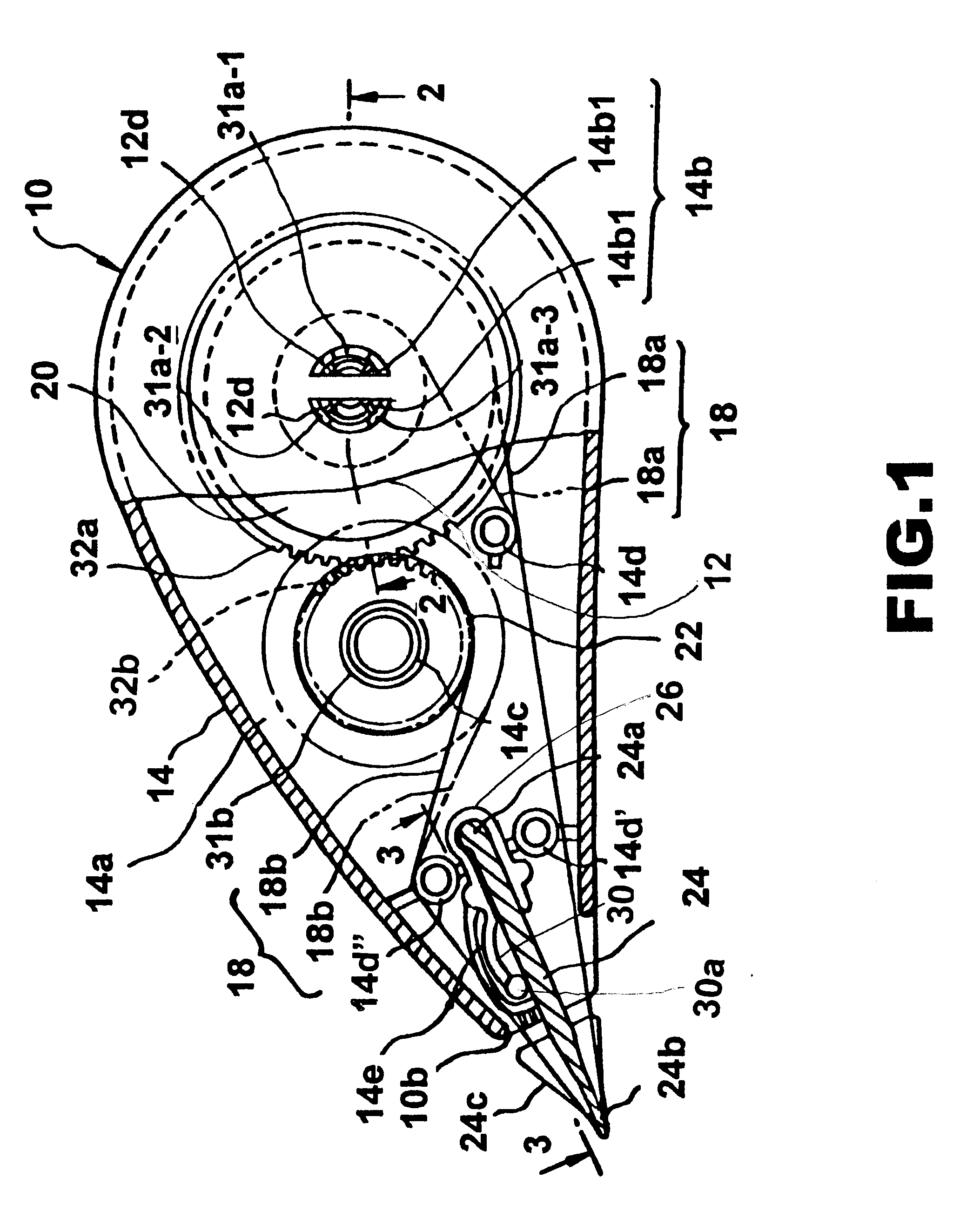
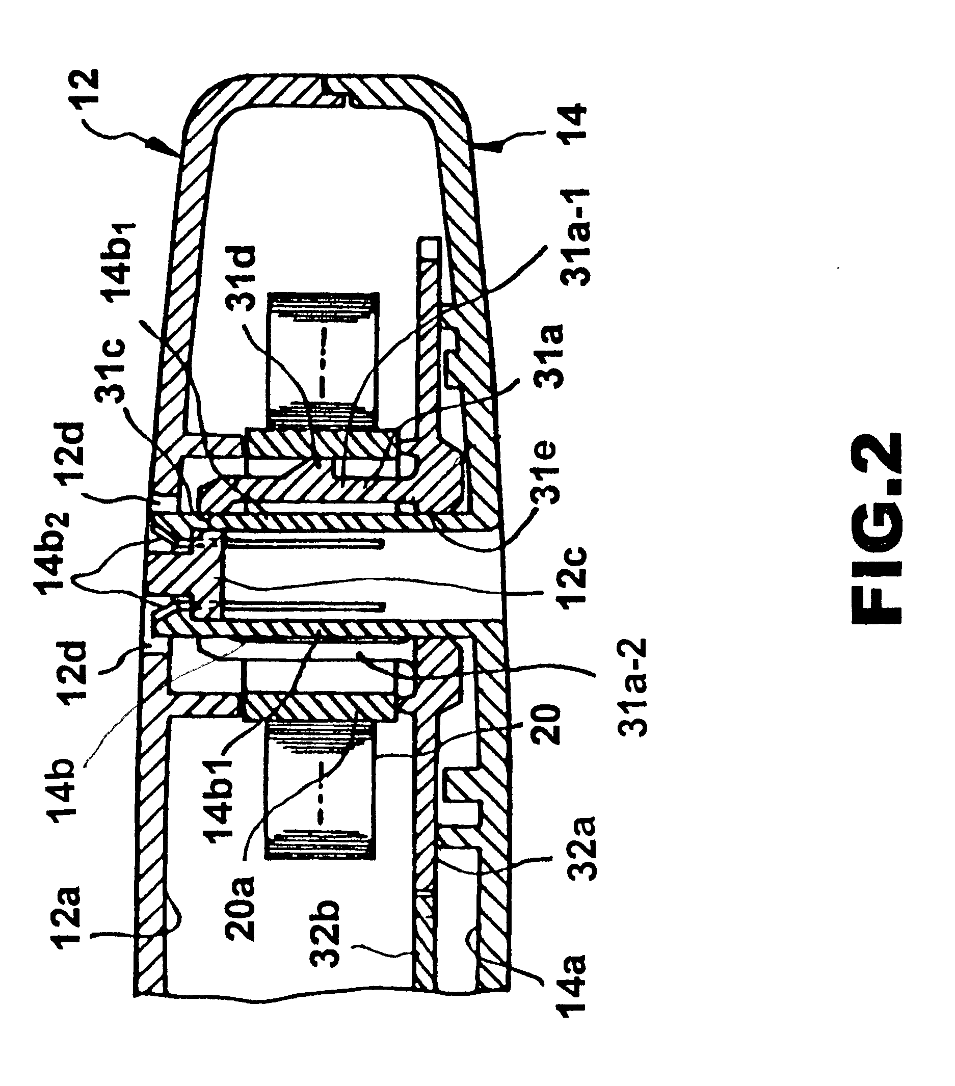
As shown in FIG. 1, the coat transfer tool has a case 10 which includes an upper case 12 and a lower case 14, which are combined to form a closed space with an opening 10b at one end of the closed space.

Within the case 10 are rotatably pivoted a feed reel 20, wound with a coat transfer tape 18a, and a takeup reel 22, for taking up a carrier film 18b, which has been fed from the feed reel 20 and whose coat of composition has been peeled off. The feed reel 20 and the takeup reel 22 are respectively fitted to boss parts 31a and 31b of gears 32a and 32b rotatably mounted on protruding shafts 14...

second embodiment

FIG. 9 illustrates a second preferred embodiment of the present invention. The same members, as in the first embodiment, are assigned the same reference numerals and, for brevity, a detailed description is not repeated.

This embodiment differs from the first embodiment in that a projection 14f as a limiting unit, extends from the edge of the side window 14e of the lower case 14. Further, the tip 30a' of the elastic pressing arm 30' does not extend to the side window 14e, and the range of displacement of the elastic pressing arm 30' is limited by the projection 14f. This embodiment provides the same effects and advantages as the first embodiment does. Many other variations are also feasible in addition to those described above.

third embodiment

The embodiment illustrated in FIG. 10, for example, differs from the first embodiment in that the elastic pressing arm 30" is separate from the lower case 14. In the base of the elastic pressing arm 30" a hole is bored having a non-circular section. In this case, a supporting pillar 14g matching the hole having the noncircular section is provided on the lower case 14. In this manner the base of the elastic pressing arm 30" is prevented from turning relative to, and is substantially fixed to, the lower case 14.

In contrast, the tip of the elastic pressing arm 30@ can be displaced along the plate-shaped part 14a of the lower case 14, as in the first embodiment. In this way, even though the elastic pressing arm 30@ is separate from the lower case 14 and the supporting body 26, effects and advantages similar to those of the first embodiment shown in FIG. 1 can be obtained.


PUM

PropertyMeasurementUnit
fluorescentaaaaaaaaaa
angleaaaaaaaaaa
elastic displacementaaaaaaaaaa

Abstract

A coat transfer tool includes a case having a plate-shaped part, a feed reel provided in the case and wound with a coat transfer tape, a takeup reel provided in the case, for taking up the carrier tape fed by the feed reel, and an applying strip disposed on the path of the tape running between the feed reel and the takeup reel and pressed against a surface of a substrate. An elastic pressing arm protrudes from the plate-shaped part of the case to be kept in contact with a surface of the applying strip and to elastically press the applying strip in a direction substantially vertical to the surface.

Description

1. Field of the InventionThe present invention relates to a coat transfer tool for serving as an eraser, marker, glue or the like by transferring a coat of, for example, correction composition, fluorescent composition or adhesive composition (hereinafter referred to as "a coat of composition") from a carrier tape to a substrate such as paper.2. Description of the Related ArtCommercially available coat transfer tools of this kind generally include a feed reel provided in a case and wound with a coat transfer tape, a takeup reel, provided in the case, for winding a carrier tape which is fed from the feed reel and whose coat of composition has been peeled off, a transmitting unit for transmitting revolutions between the feed reel and the takeup reel and an applying strip disposed on the path of the tape running between the feed reel and the takeup reel and adapted to be pressed against a surface of a substrate, for example, a paper surface to transfer the coat onto the substrate surfac...

Claims


Application Information

Patent Timeline
Patent Type & Authority Patents(United States)
IPC IPC(8): B65H37/00B43L19/00B43K8/00B43M11/06B65H35/07
CPCB65H37/007Y10T156/18Y10T156/1795Y10T156/1348
Inventor KAGEYAMA, HIDEHEIANZAI, SADAHIROMITSUYA, YOSHIHIDE
Owner KOTOBUKI & CO LTD
Why Eureka
Try Eureka