Die inner cutting forming device of forming machine

A molding machine and mold table technology, which is applied in the field of in-mold cutting and forming devices, can solve the problems of thin ring cutters, impossibility of implementation, bending of ring cutters, etc., and achieve high stability.

Active Publication Date: 2016-01-20
广东金兴机械股份有限公司
View PDF6 Cites 8 Cited by
  • Summary
  • Abstract
  • Description
  • Claims
  • Application Information

AI Technical Summary

Problems solved by technology

[0004] There are currently two ideas for combining the forming device and the cutting device into one, but these two ideas are basically impossible to implement
[0005] One of the ideas is: set a ring cutter on the upper mold, cut the plastic sheet into corresponding blocks when closing the mold, and then press the block plastic sheet through the upper mold and the lower mold to make the edge Sealing, and then plastic molding, since there is a need for sealing edge, it will obviously produce edge material around the product, which is an impractical solution
[0006] Another idea is to install a cutter driving device for driving the ring cutter on the upper mold. After the upper mold and the lower mold are molded and formed, the ring cutter is independently driven by the cutter drive device to cut the plastic sheet. Cut off, so theoretically possible, but not feasible
Because the cutter drive device for driving the ring cutter is installed on the mold, which in itself greatly increases the complexity of the upper mold. More importantly, the ring cutter is generally very thin, and the ring cutter has no other features. The carrier, without a protective structure, is very likely to cause bending or other damage to the circular cutter during the downward cutting process, or it may not cut at all. Therefore, it is not feasible to independently drive the circular cutter with a cutter driving device

Method used


Image

  • Die inner cutting forming device of forming machine
  • Die inner cutting forming device of forming machine
  • Die inner cutting forming device of forming machine

Examples


Embodiment Construction

[0026] Further description will be given below in conjunction with the accompanying drawings and preferred embodiments of the present invention.

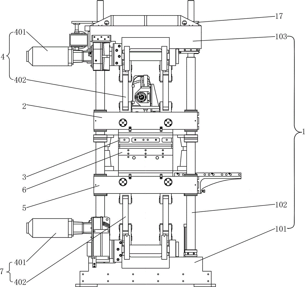
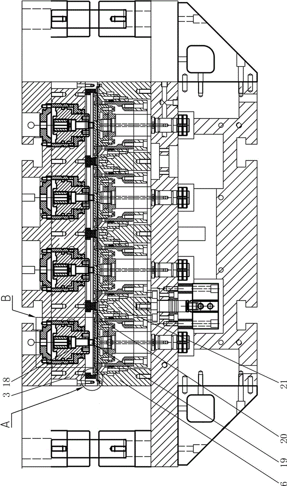
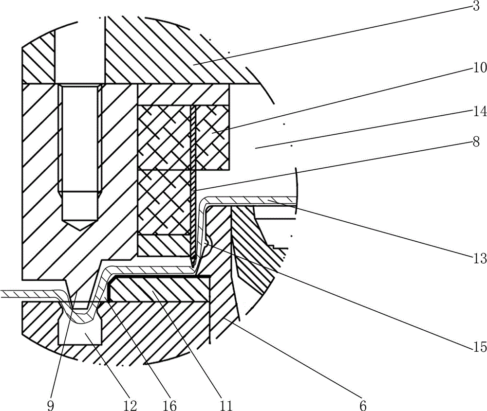
[0027] Such as figure 1 , figure 2 , image 3 and Figure 4 As shown, the in-mold cutting molding device of this molding machine includes a frame 1, an upper mold table 2, an upper mold 3, an upper mold table driving mechanism 4, a lower mold table 5, a lower mold 6 and a lower mold table driving mechanism 7. The lower mold 5 is a punch made of metal; the frame 1 includes a base 101, a top seat 102 and a plurality of guide pillars 103, and the guide pillars 103 are installed between the base 101 and the top seat 102, and the upper mold table driving mechanism 4 , lower mold platform driving mechanism 7 are respectively installed on top 102, base 101, upper mold platform driving mechanism 4, lower mold platform driving mechanism 7 all comprise servo motor 401 and linkage mechanism 402, servo motor 401 and linkage mechanism 402 T...


PUM


Abstract

The invention relates to a die inner cutting forming device of a forming machine. The die inner cutting forming device of the forming machine comprises a machine frame, an upper die platform, an upper die, an upper die platform driving mechanism, a lower die platform, a lower die and a lower die platform driving mechanism, wherein the upper die is provided with an annular laser cutter and an annular protruding strip, and the annular protruding strip is located on the outer side of the annular laser cutter; the lower die is provided with an annular cutter chop board and an annular groove which correspond to each other. During forming lifting control, the annular laser cutter does not cut off a plastic sheet but just tightly presses the plastic sheet to form sealing, so that the sealing during plastic uptake forming is achieved. The annular groove and the annular protruding strip form auxiliary sealing, so that the stability of plastic uptake forming is improved. The annular laser cutter is directly arranged on the upper die, the structure is simpler, the problems that as the annular laser cutter is too thin, the annular laser cutter is prone to being bent and cannot cut off the plastic sheet are solved, and the plastic sheet can be cut off more orderly and stably. After a product is formed, the product is cut on the forming device, the production efficiency is improved, and the manufacturing cost of the whole machine is lowered. Besides, the overall machine structure is simpler and more compact, and the occupied space is reduced.

Description

technical field [0001] The invention relates to a molding device, in particular to an in-die cutting molding device of a molding machine. Background technique [0002] At present, the blister forming production equipment used for the production of plastic products usually includes an unwinding device, a heating device, a forming device, a cutting device and a collecting device, and some blister forming production equipment also includes a punching device. The cutting device and the forming device are two independent parts. After the product is formed, it is transported to the cutting device for cutting, and each product is cut out. This leads to lower production efficiency, and because the structure of the cutting device is basically the same as that of the forming device, the whole machine occupies a larger area, resulting in a waste of land resources. [0003] At present, there is no feasible technical solution for combining the forming device and the cutting device. This...

Claims


Application Information

Patent Timeline
Patent Type & Authority Applications(China)
IPC IPC(8): B29C51/18B29C51/32B29C51/26
Inventor 蔡健伟
Owner 广东金兴机械股份有限公司
Why Eureka
Try Eureka