Device for clipping rubber rings

A technology of a rubber ring and a driving device is applied in the processing field of rubber rings, which can solve the problem of not being able to cut multiple rubber rings at the same time, and achieve the effects of simple structure, convenient operation and neat position.

Active Publication Date: 2014-10-29
ANHUI JINGHONG SEAL TECH
View PDF10 Cites 7 Cited by
  • Summary
  • Abstract
  • Description
  • Claims
  • Application Information

AI Technical Summary

Problems solved by technology

This technical solution is not suitable for cutting the above-mention

Method used


Image

  • Device for clipping rubber rings
  • Device for clipping rubber rings
  • Device for clipping rubber rings

Examples


Example Embodiment

[0020] Example 1:

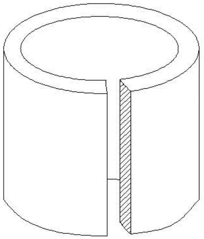
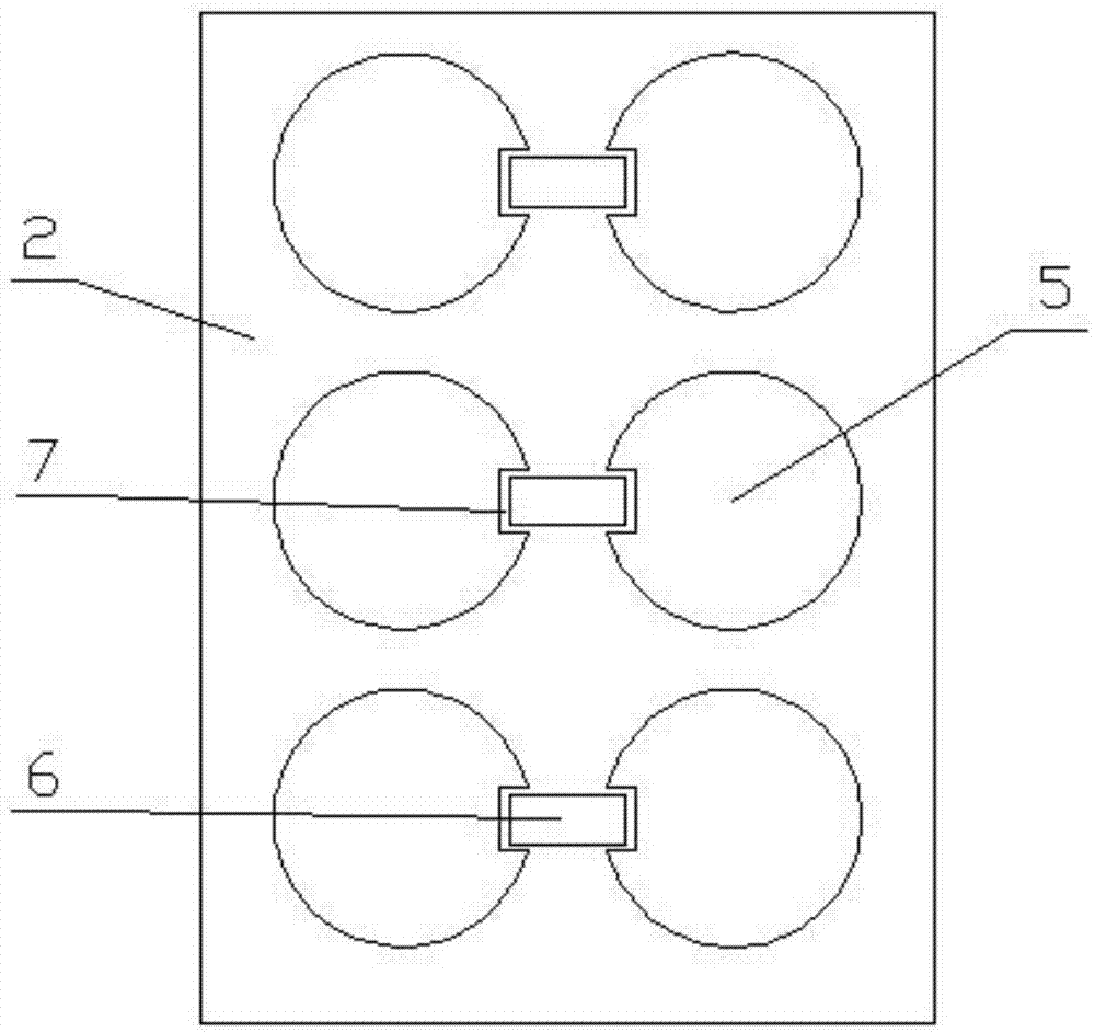
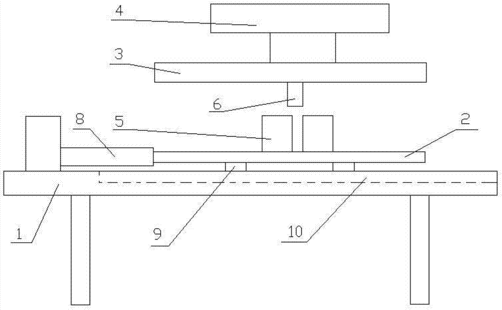
[0021] combine figure 1 , figure 2 , image 3 : A device for cutting rubber rings, involving rubber rings, including a workbench 1, a bottom plate 2, a pressing plate 3, a driving device 4, a number of cylinders 5, a number of blades 6, a hydraulic cylinder 8, and the bottom plate 2 placed on the workbench 1 surface, the cylinder 5 is arranged on the bottom plate 2, each cylinder 5 is provided with a groove 7 along the axial direction, the length of the groove 7 is not less than the height of the rubber ring, and the width of the groove 7 is not less than the blade 6 The thickness of the cylinder 5 is equal to the inner diameter of the rubber ring; the pressure plate 3 is placed above the bottom plate 2, the blade 6 is installed at the bottom of the pressure plate 3, the blade 6 is placed above the groove 7, and the output of the pressure plate 3 and the drive device 4 end connection.

[0022] Put the rubber ring on the cylinder, push the pressing plat...

Example Embodiment

[0027] Example 2:

[0028] combine figure 1 , Figure 4 , Figure 5 : A device for cutting rubber rings, involving rubber rings, including a workbench 1, a bottom plate 2, a pressing plate 3, a driving device 4, a number of cylinders 5, a number of blades 6, a hydraulic cylinder 8, and the bottom plate 2 placed on the workbench 1 surface, the cylinder 5 is arranged on the bottom plate 2, each cylinder 5 is provided with a groove 7 along the axial direction, the length of the groove 7 is not less than the height of the rubber ring, and the width of the groove 7 is not less than the blade 6 The thickness of the cylinder 5 is equal to the inner diameter of the rubber ring; the pressure plate 3 is placed above the bottom plate 2, the blade 6 is installed at the bottom of the pressure plate 3, the blade 6 is placed above the groove 7, and the output of the pressure plate 3 and the drive device 4 end connection.

[0029] Put the rubber ring on the cylinder, push the pressing pla...


PUM


Abstract

The invention discloses a device for clipping rubber rings, and relates to rubber rings. The device comprises a workbench, a base plate, a pressing plate, a driving device, a plurality of column bodies and a plurality of blades. The base plate is arranged on the surface of the workbench. The column bodies are arranged on the base plate. Each column body is provided with a groove in the axial direction. The length of the grooves is not smaller than the height of the rubber rings. The width of the grooves is not smaller than the thickness of the blades. The diameter of the column bodies is equal to the inner diameter of the rubber rings. The pressing plate is arranged above the base plate. The blades are installed at the bottom of the pressing plate. The blades are arranged above the grooves. The pressing plate is connected with the output end of the driving device. According to the device clipping the rubber rings, the rubber rings can be clipped at the same time, the speed is high, efficiency is high, labor intensity of workers is relieved, the clipping positions are in order and are attractive, the consistency is good, the structure is simple and practical, the cost is low, and operation is convenient.

Description

technical field [0001] The invention relates to the technical field of processing rubber rings, in particular to a device for cutting rubber rings. Background technique [0002] Such as figure 1 As shown, the edge of the rubber ring needs to be cut off for easy installation after processing. In the prior art, the edge of the rubber ring is cut off manually with scissors. Obviously, this operation method is inconvenient for cutting, and multiple rubber rings cannot be cut at the same time, and the efficiency is low. [0003] In the Chinese patent application number: 201110237393, an automatic rectangular rubber ring cutting machine is disclosed, which includes a machine base and a cutting device connected to the control system. One end of the machine base is provided with a shaft box connected to the motor, and the other end of the machine base is provided with a feeding machine. device, the feeding device includes a bracket and a feeding mechanism arranged on the bracket a...

Claims


Application Information

Patent Timeline
IPC IPC(8): B26D1/04B26D7/01
Inventor 汪洪
Owner ANHUI JINGHONG SEAL TECH
Why Eureka
Try Eureka