Gauge mounted pressure monitor and alarm for compression mounting with compressed gas storage tank

a technology of pressure monitor and compression mounting, which is applied in the direction of fluid pressure measurement, instrumentation, container discharge methods, etc., can solve the problems of difficult to read gauges, poor eyesight, and slow operation of users

Inactive Publication Date: 2001-12-04
INGEN TECH
View PDF11 Cites 32 Cited by
  • Summary
  • Abstract
  • Description
  • Claims
  • Application Information

AI Technical Summary

Benefits of technology

FIG. 5 is a cut away side view of the ala

Problems solved by technology

This mode of operation, while quick for the user, also has its drawbacks.
Pressure gauges now conventionally attached to a port in the regulator communicating with the high incoming pressure from the tank, can be hard to read by users with poor eyesight.
Such gauges can also be hard to understand for those who are not technically oriented, or do not know what a safe operating pressure actually is for the supply tank or cylinder.
Such users may be of ill health from a pulmonary or cardiovascular disease and severely dependent upon a reliable and continued oxygen supply.
To allow the pressure to dissipate entirely in a medical or emergency situation would risk the user's life support provided by the supply of oxygen.
Failure to maintain adequate supplies of oxygen and other gases in industrial and military situations can be costly in time and money from resulting downtime.
The most dependent users of such oxygen supplies are generally health impaired, aged, and/or not technically oriented.
Other users in emergencies or industrial situations may

Method used


Image

  • Gauge mounted pressure monitor and alarm for compression mounting with compressed gas storage tank
  • Gauge mounted pressure monitor and alarm for compression mounting with compressed gas storage tank
  • Gauge mounted pressure monitor and alarm for compression mounting with compressed gas storage tank

Examples


Embodiment Construction

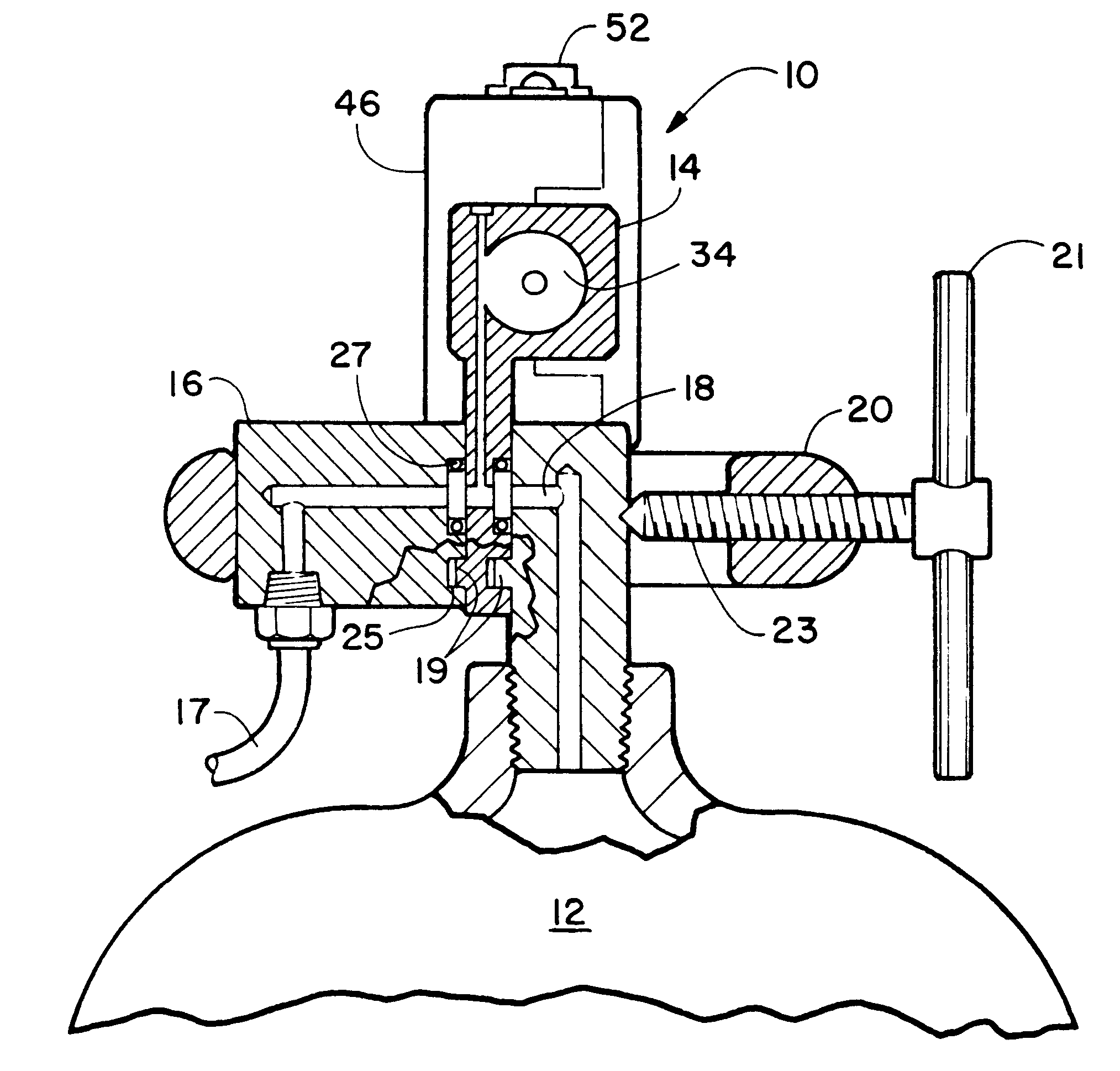
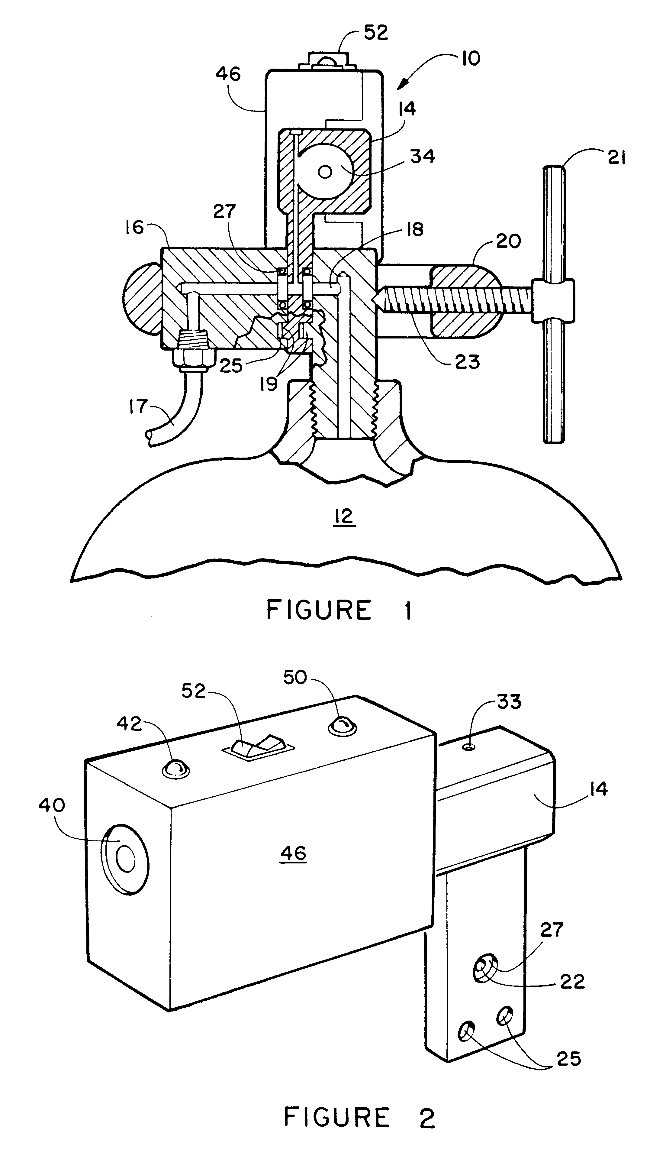
Referring now to the drawing FIGS. 1-7, specifically FIG. 1 depicts a side view of the compression mounted warning device 10 herein disclosed in operative engagement with a conventional pressurized gas tank 12.

The device 10 features a manifold 14 that is capable of operative engagement with the regulator 16 and the orifice at tank outlet orifice 18. A conventionally used compression clamp 20 is used to operatively engage the device 10 and the regulator 16 with gas outlet 17 and the tank outlet orifice 18 in an operative engagement while still providing for a removable mount of the devices, to the tank outlet orifice 18 by removal of the compression clamp 20. The device 10 is configured to allow for inclusion into this operatively connected tank outlet orifice 18 and regulator 16 mating, without any modification to either the tank outlet orifice 18, the clamp 20, or the regulator 16. Extra clearance for the clamp 20 may be optionally provided by slots 21 in the manifold exterior if n...


PUM


Abstract

A warning device configured for removable mounting in combination with a high pressure gas cylinder and a regulator used to regulate the high pressure gas supplied by the cylinder. The device compression mounts between the regulator and tank outlet on conventional portable oxygen and gas supply systems using a specially configured manifold. The device features one or a combination of alarms, from a group including audio, visual, electronic, and remotely transmitted alarms. These alarms are activated by a pressure switch monitoring the remaining supply in the gas cylinder through a conduit the manifold. The alarm signal from the device alerts the user, or a third party monitoring the user, of current tank pressure or will sound an alarm when remaining high pressure gas inside the gas cylinder drops below a predetermined level.

Description

BACKGROUND OF INVENTION1. Field of InventionThe present invention relates to pressure sensing equipment for use with cylinders and tanks which hold compressed gas for dispersion under a lower and regulated pressure. More particularly, it relates to a device configured for removable mounting in combination with a portable high pressure gas cylinder and a regulator used to regulate the high pressure gas supplied by the cylinder. Such portable gas tanks or cylinders are commonly used to provide a portable oxygen supply to a user requiring such. The device features one or a combination of alarms, from a group of alarms including audio, visual, electronic, and remotely transmitted alarms. The alarm signal from the device alerts the user, or a third party monitoring the user, when remaining high pressure gas inside the gas cylinder drops below a predetermined level.2. Prior ArtCylinders and tanks containing pressurized gasses are used throughout the industrialized world in industry and me...

Claims


Application Information

Patent Timeline
IPC IPC(8): G01L19/12G01L19/00
CPCF17C13/003G01L19/12F17C1/00F17C2201/0109F17C2201/058F17C2203/0617F17C2205/0329F17C2205/0338F17C2205/0382F17C2205/0394F17C2221/011F17C2223/0123F17C2223/036F17C2250/034F17C2250/036F17C2250/043F17C2250/077F17C2270/025F17C2270/079Y10T137/8326
Inventor MCDERMOTT, FRANCIS FRITZMCDERMOTT, BETTIE
Owner INGEN TECH
Why Eureka
Try Eureka