
Adjustable computer stand

a computer and adjustable technology, applied in the direction of machine supports, adjustable height tables, other domestic objects, etc., can solve the problems of hot bottom of laptop computers, unsuitable keyboard positions, and user's legs starting to bum,

Inactive Publication Date: 2001-12-11
JACKSON STEPHEN
View PDF10 Cites 84 Cited by
  • Summary
  • Abstract
  • Description
  • Claims
  • Application Information

AI Technical Summary

Benefits of technology

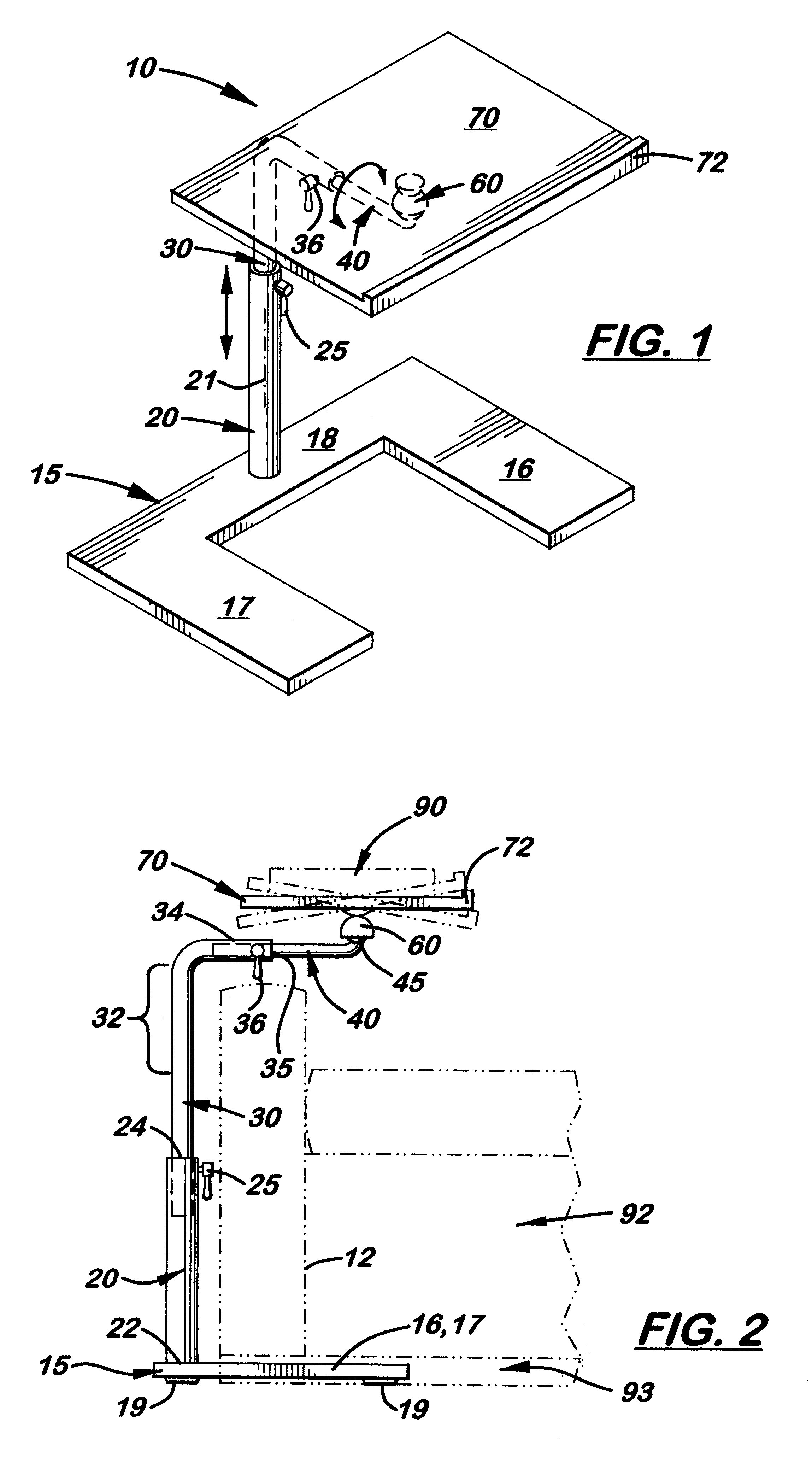
, which will become apparent, are met by the computer stand disclosed herein. The computer stand is used to support a laptop computer or keyboard over a user's lap while sitting in a chair or bed. The stand includes a wide, low profile base designed to extend into the short open area located under a chair or bed commonly found in a home. Attached perpendicularly to the base is a vertically aligned fixed pole. The fixed pole is attached to the rear member on the base so that the side members on the base may be placed under the chair and the fixed pole may be placed immediately adjacent to the side of the chair. By placing the base under the chair, the stand is able to remain upright during use.
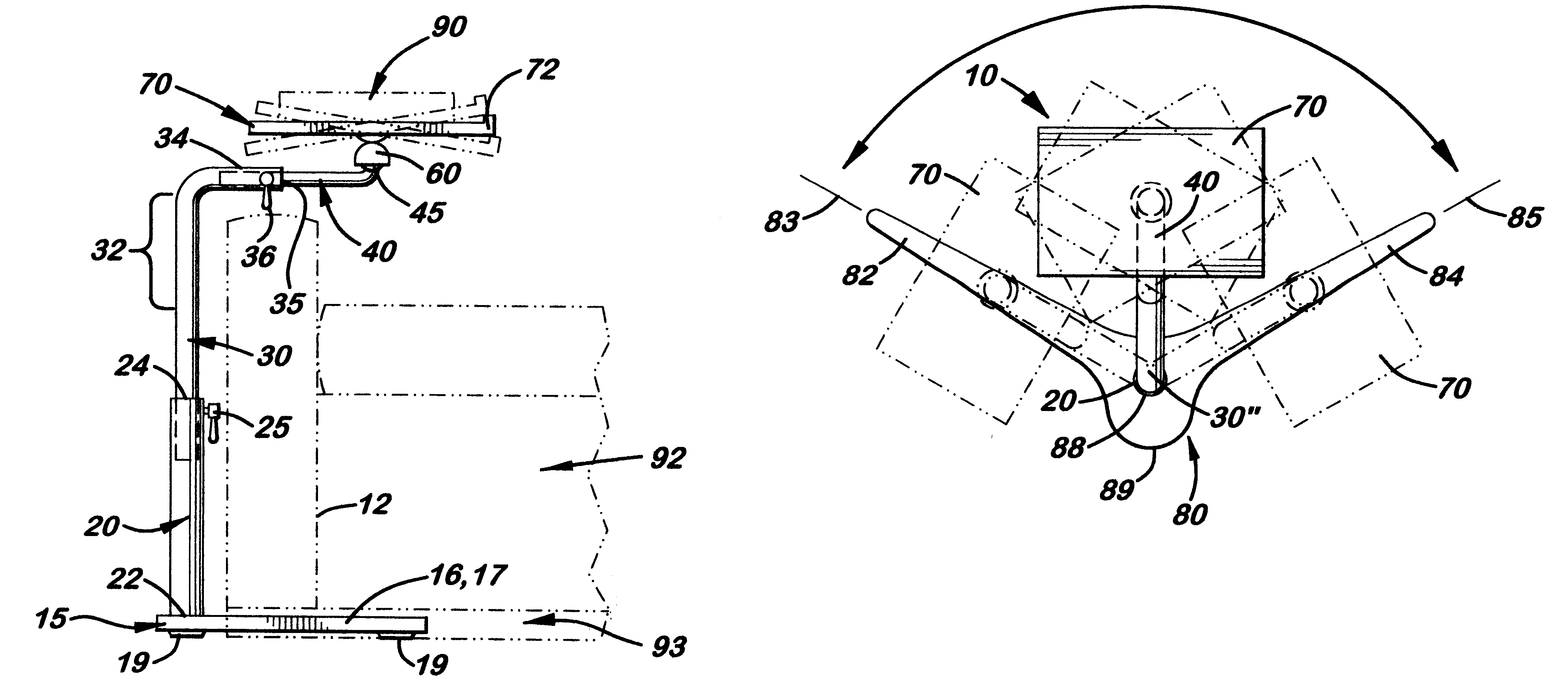
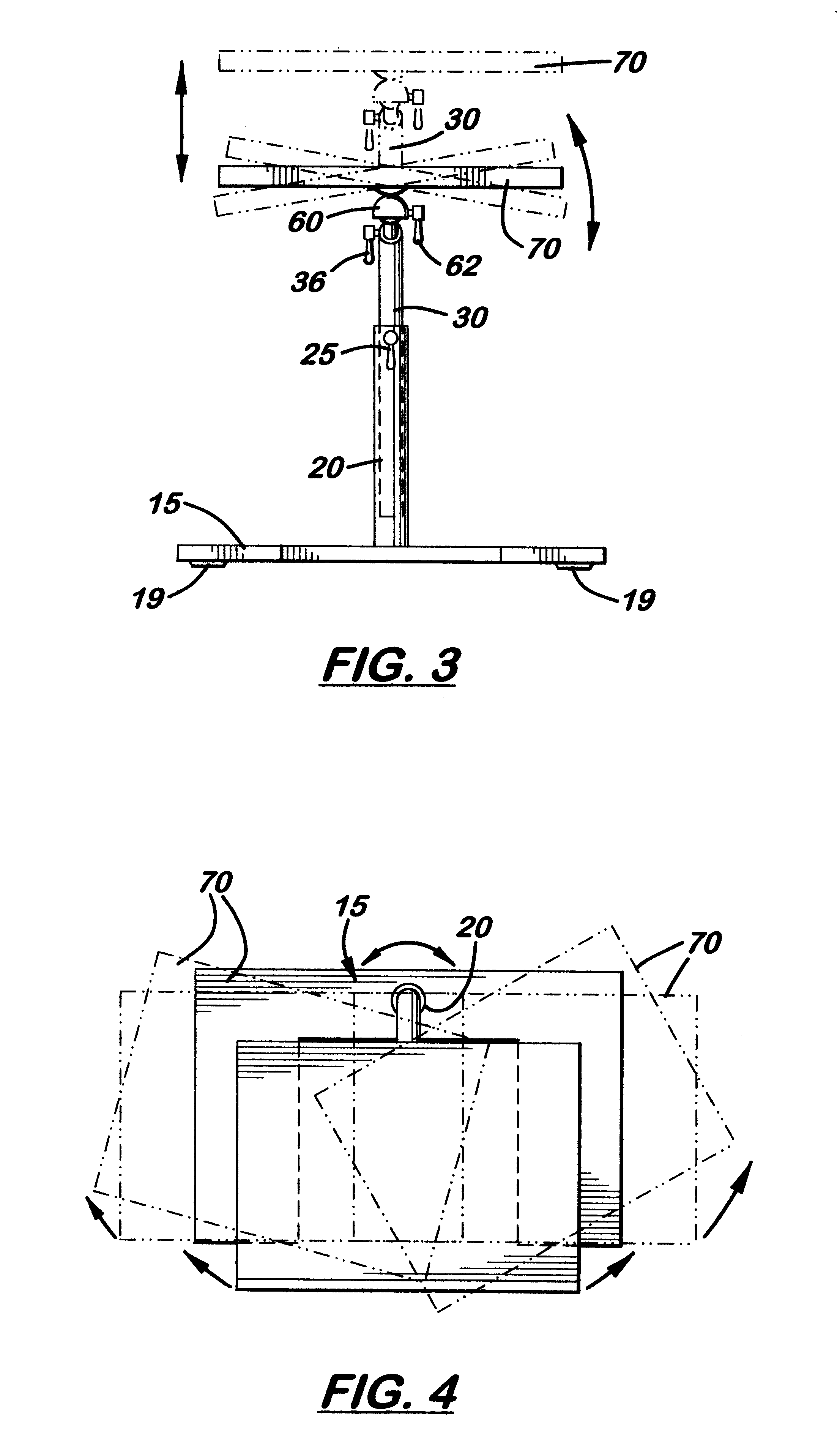
Attached to the distal end of the extension pole is an adjustable extension arm that holds the support surface horizontally over the edge or seat of the chair or bed. In the preferred embodiment, the fixed extension pole and extension arm are both circular in cross section. During use, the extension arm is able to rotate and slide longitudinally inside the upper section of the extension pole, thereby enabling the relative position of the support member to the fixed pole to be selectively adjusted by the user. A locking means is disposed between the distal end of the extension pole and the proximal end of the extension arm thereby enabling the extension arm to be locked in a desired position on the extension pole. In a second embodiment, a pivoting means is provided between the extension pole and extension arm that enables the proximal end of the extension arm to pivot 360 degrees around a vertical axis. In a third embodiment, the base is Y-shaped with two extending legs aligned longitudinally at least 90 degrees apart, so that the base can be positioned around a corner leg on the chair. Limiting means are disposed between the fixed pole and extension pole that limit the arc of rotation of the extension pole over the fixed pole to the two leg members on the base so that the stand does not tip over during use.
FIG. 5 is a top plan view of a second embodiment of the extension arm that allows additional rotation of the support member.

Problems solved by technology

Unfortunately, in a short time the bottom of the laptop computer becomes hot and begins to bum the user's legs.
Also, the position of the keyboard is unsuitable for proficient typing.

Method used


Image

  • Adjustable computer stand
  • Adjustable computer stand
  • Adjustable computer stand

Examples


first embodiment

Referring to the accompanying FIGS. 1-10, there is shown and described a computer stand generally referenced as 10 used to support a laptop computer or keyboard over a user's lap while sitting in chair 92 or bed. The stand 10 includes a wide, low profile base 15 designed to extend into the narrow space 93 created under a chair 92 (see FIG. 2) or bed. In the first embodiment, the base 15 is U-shaped with two parallel side members 16, 17, and one perpendicularly aligned rear member 18. The base 15 includes four short feet 19, measuring approximately 1 / 2 inch in height, attached to the bottom surface to reduce friction and prevent scratching of the floor during use. The overall dimensions of the base 15 are 20 inches by 13 inches (L.times.W) and 3 / 4 inch in thickness. It is made of heavy material such as polished or painted steel, to act as a counter weight to support light pressure exerted by the laptop computer or the user's hands and arms.

Attached perpendicularly to the base 15 is a...

second embodiment

In a second embodiment shown in FIGS. 5 and 6, the extension arm 40 is replaced with a two-piece extension arm 50 that only rotates 360 degrees around a vertical axis 37 located near the distal end 35 of the extension pole 30. The extension arm 50 includes a perpendicularly aligned neck 52 that extends downward and is inserted into a bore 38 formed on the extension pole 30. During assembly, the neck 52 is extended into the bore 38 to allow the extension arm 50 to rotate as shown in FIG. 5. A locking latch 36 is then used to lock the extension arm 50 in position on the extension pole 30.

third embodiment

FIGS. 8, 9 and 10 show the computer stand 10 which uses a Y-shaped base 80, a fixed pole 20, and a curved extension pole 30". Attached to the upper end of the extension pole 30" is the extension arm 40 or extension arm 50 (not shown). The base 80 also includes two elongated arms 82, 84 and a central short leg 86. Formed on the distal end of the pole 30" are two stop surfaces 88, 89, which act to limit the rotation of the extension pole 30" between the longitudinal axis 83, 85 of the arms 82, 84, respectively, and to prevent the stand 10 from tipping over during use.


PUM


Abstract

This invention is an adaptable computer stand designed to support a laptop computer or keyboard over a user's lap while sitting in a chair or bed. The stand includes a wide, low profile base designed to fit under a living room chair commonly found in a home. Attached perpendicularly to the base is a vertically aligned, fixed pole. Attached to the upper end of the fixed pole is an adjustable, L-shaped extension pole designed to be selectively raised or lowered on the fixed pole, rotate, and then lock in a desired position. Attached to the upper end of the extension pole is a length-adjustable, rotating extension arm. The stand also includes a planar support member used to support a keyboard or laptop computer. Attached to the bottom surface of the support member is a locking universal joint, which, during assembly, is connected to the distal end of the extension arm. The universal joint enables the support member to tilt and rotate as desired.

Description

1. Field of the InventionThis invention pertains to stands or supports used to hold a laptop computer or keyboard.2. Description of the Related ArtToday, laptop computers are commonly used in homes and motel rooms without a desk or table. When used while sitting in a chair or bed, the laptop computer must be supported on the user's lap. Unfortunately, in a short time the bottom of the laptop computer becomes hot and begins to bum the user's legs. Without a mouse support surface, the user is also forced to use the touch pad or point stick provided with the laptop computer. Also, the position of the keyboard is unsuitable for proficient typing.Portable food stands are widely used in hospitals to support a tray of food for a patient lying in a bed. Because hospital beds have tall open areas under the bed frame, the legs on the stands are able to freely extend under the bed to position the food tray over the patient.The height and design of chairs and beds at home varies greatly and do ...

Claims


Application Information

Patent Timeline
Patent Type & Authority Patents(United States)
IPC IPC(8): A47B23/04A47B23/00
CPCA47B23/046
Inventor JACKSON, STEPHEN
Owner JACKSON STEPHEN
Learn More