Temperature-responsive mixing valve

a technology of temperature-responsive and mixing valve, which is applied in the direction of thin material processing, process and machine control, instruments, etc., can solve the problems of consuming this extra travel, and affecting the quality of the finished produ

Inactive Publication Date: 2001-12-11
HILCO CAPITAL
View PDF17 Cites 17 Cited by
  • Summary
  • Abstract
  • Description
  • Claims
  • Application Information

AI Technical Summary

Benefits of technology

to provide a mixing valve which is compact.

Problems solved by technology

A common problem in the use of such devices is that if the shuttle has moved as far as it can move within the valve, but the piston of the thermal actuator is still trying to move, there must be some means of consuming this extra travel.
Otherwise the valve can be damaged or destroyed.
This solution creates several additional problems.
First, this arrangement adds height to the mixing valve, which may prevent or restrict use in confined areas, or promote breakage under impact.
Second, the overtravel spring must be preloaded, requiring a means for retaining the spring on the adjusting bolt.
In addition, mixing valves are often difficult to disassemble for repair or maintenance, and require the use of tools, often in confined spaces.

Method used


Image

  • Temperature-responsive mixing valve
  • Temperature-responsive mixing valve
  • Temperature-responsive mixing valve

Examples


Embodiment Construction

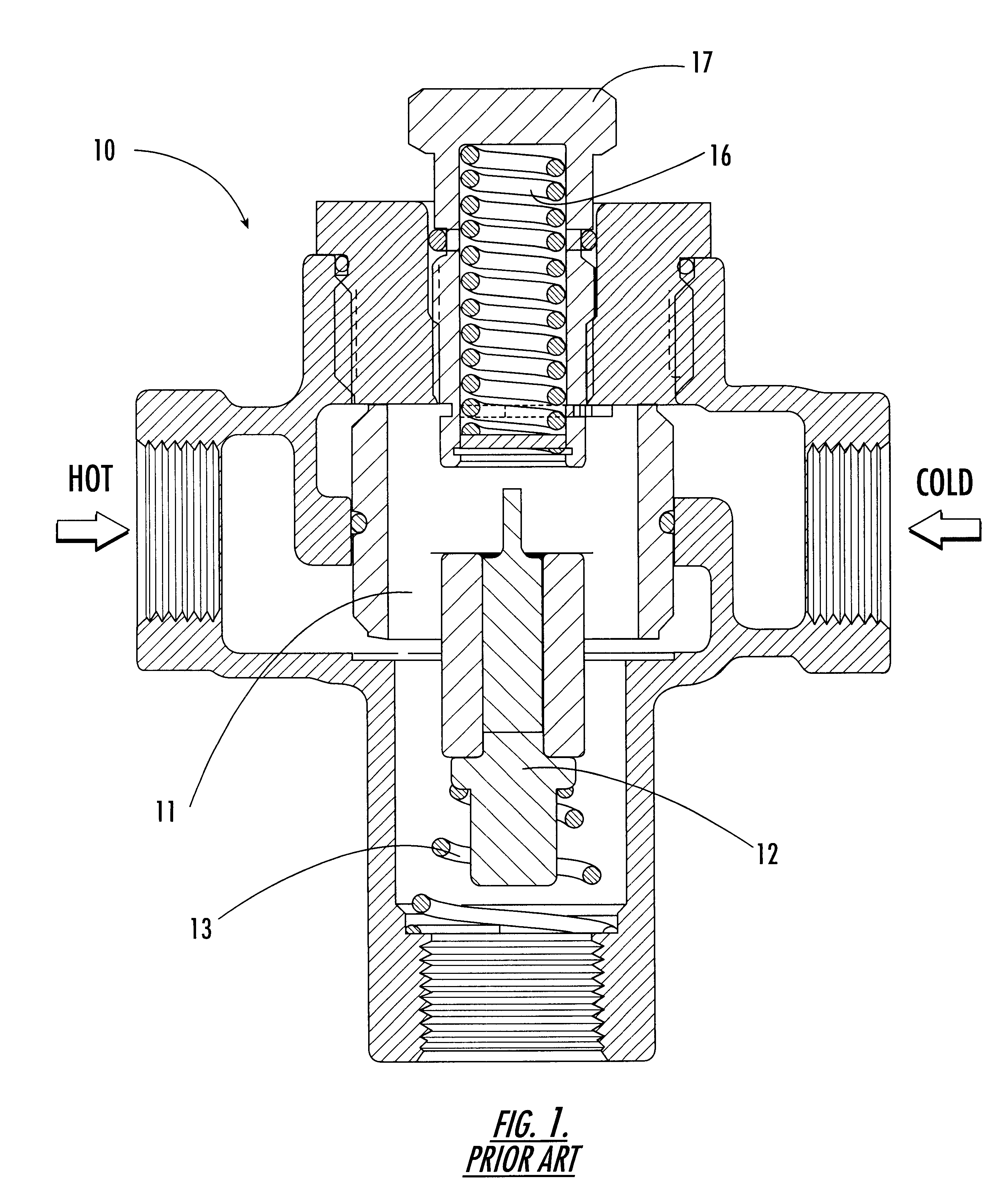
Referring now specifically to the drawings, a prior art temperature-responsive mixing valve 10 is shown. Note generally that the prior art shuttle assembly 11 is moved by a thermal actuator 12 which is maintained in a tensioned condition by a spring 13, which returns the thermal actuator 12 to its initial position. Another spring 16 captured on the other side of the thermal actuator 12 by an adjustment bolt 17 provides overtravel protection to the shuttle assembly 11. This arrangement results in a valve housing which is relatively large, as is evident from the overall length taken up by the shuttle assembly, spring 13 and spring 16. The shuttle assembly 11 is rigidly attached via a threaded connection to the thermal actuator 12.

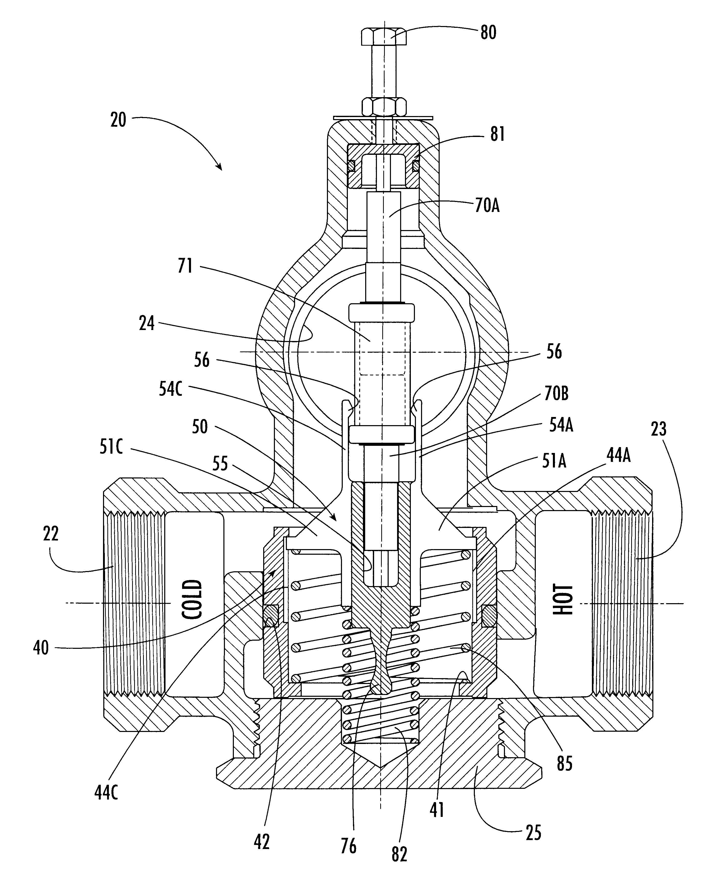
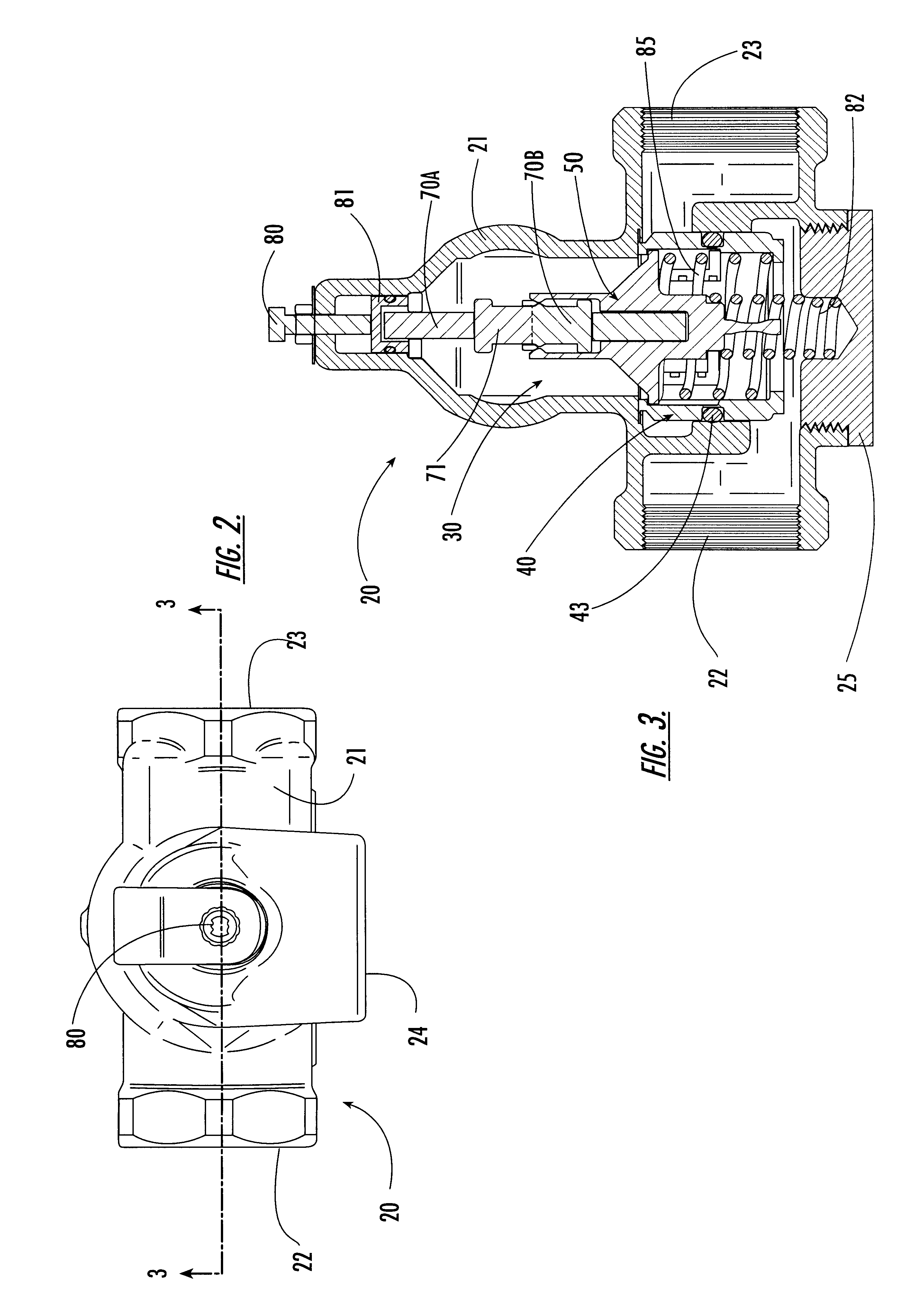
As is shown in FIGS. 2-13, the mixing valve 20 according to a preferred embodiment of the invention is simple, compact, efficient and easy to assemble and disassemble. As is generally shown in FIGS. 2 and 3, mixing valve 20 includes a cast housing 21 which in...


PUM


Abstract

A temperature-actuated mixing valve for controlling outlet temperature in a fluid flow system including a valve housing having first and second fluid supply inlets for introducing first and second respective supply fluids and a fluid outlet for dispensing a fluid at a predetermined outflow temperature. The mixing valve includes a shuttle assembly positioned in the housing. The shuttle assembly includes a valve member mounted for movement within the housing responsive to the temperature of the supply fluids to vary the mixture ratio of the first and second supply fluids as required to dispense fluid at the predetermined outflow temperature. A shuttle member is positioned within the valve member and is moveable as a unit therewith within a predetermined range of motion responsive to supply fluid temperature variation. A thermal actuator is provided of the type which converts thermal energy into mechanical movement by movement of a piston. A first end of the thermal element engages the movable shuttle member and an opposing second end engages a stationary portion of the housing whereby movement of the piston of the thermal actuator produces corresponding movement of the valve member. An overtravel spring is captured in a tensioned condition between the valve member and the shuttle member for maintaining the shuttle member and the valve member in a stationary condition relative to each other within the predetermined range of motion of the valve member and for permitting movement of the shuttle member relative to the valve member sufficient to accommodate movement of the piston of the thermal actuator when the valve member has reached its limit of travel without accommodating the full extent of movement of the piston of the thermal actuator.

Description

TECHNICAL FIELD AND BACKGROUND OF THE INVENTIONThis invention relates to a temperature-actuated mixing valve of the general type used to control in-line water temperature in potable hot water systems. Such valves are typically used at the hot water source, such as at a gas or electric hot water heater or boiler. The temperature of the water allowed to flow downstream from the mixing valve is maintained within a predetermined range of temperature by mixing hot and cold water entering the valve on the upstream end. The invention is therefore described with reference to such a hot water system. However, principles of the invention also have application with other liquids and with gases, and for this reason the application is intended to encompass both liquids and gases, and liquids other than water.Most prior art mixing valves utilize a thermal actuator, which acts as the "motor" of the valve. Such actuators convert thermal energy into mechanical movement. The operating principle of mo...

Claims


Application Information

Patent Timeline
Patent Type & Authority Patents(United States)
IPC IPC(8): G05D23/13G05D23/01
CPCG05D23/1346Y10T137/0491Y10T137/6017
Inventor TAYLOR, GARETH P.TEAGUE, JR., RALPH T.
Owner HILCO CAPITAL
Why Eureka
Try Eureka