
Thermal retention-device

a technology of thermal retention device and device, which is applied in the direction of ovens, lighting and heating apparatus, ovens, etc., can solve the problems of substantial period of time between the time of energy application and the use of the device, and the limitations of the devi

Inactive Publication Date: 2001-12-11
PHASE CHANGE ENERGY SOLUTIONS INC
View PDF74 Cites 26 Cited by
  • Summary
  • Abstract
  • Description
  • Claims
  • Application Information

AI Technical Summary

Benefits of technology

Enables heating and prolonged heat retention for two to three hours, allowing use in various settings without access to a microwave oven, and can be adapted for diverse applications like clothing, food warmers, and toys.

Problems solved by technology

While prior art microwave thermal retention devices are acceptable for many uses, there are certain applications where such devices have limitations.
For many users, access to a microwave oven is not practical.
Also, for many users, there may be a substantial period of time between which the energy is applied and the device is to be used.
An example of such an inconvenience is where a thermal retention device is to be used as a cushion for either outdoor activity or for stadium use at sporting events and the like.
In such cases, there may be a substantial period of time between the application of energy to the device and the use of the device.

Method used


Image

  • Thermal retention-device
  • Thermal retention-device
  • Thermal retention-device

Examples


first embodiment

A. First Embodiment

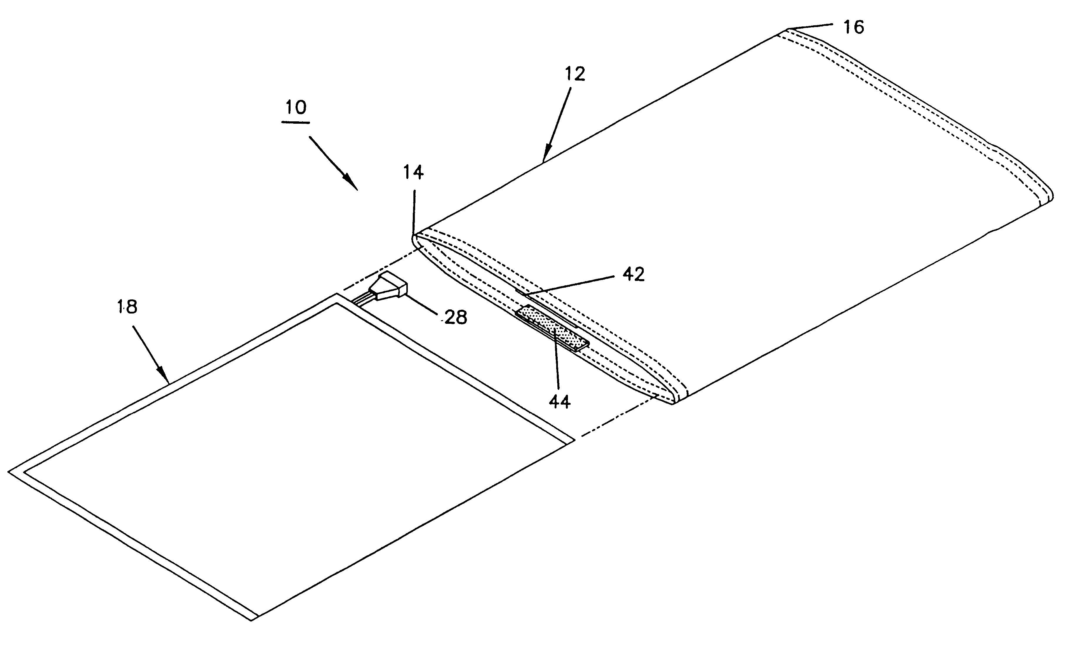
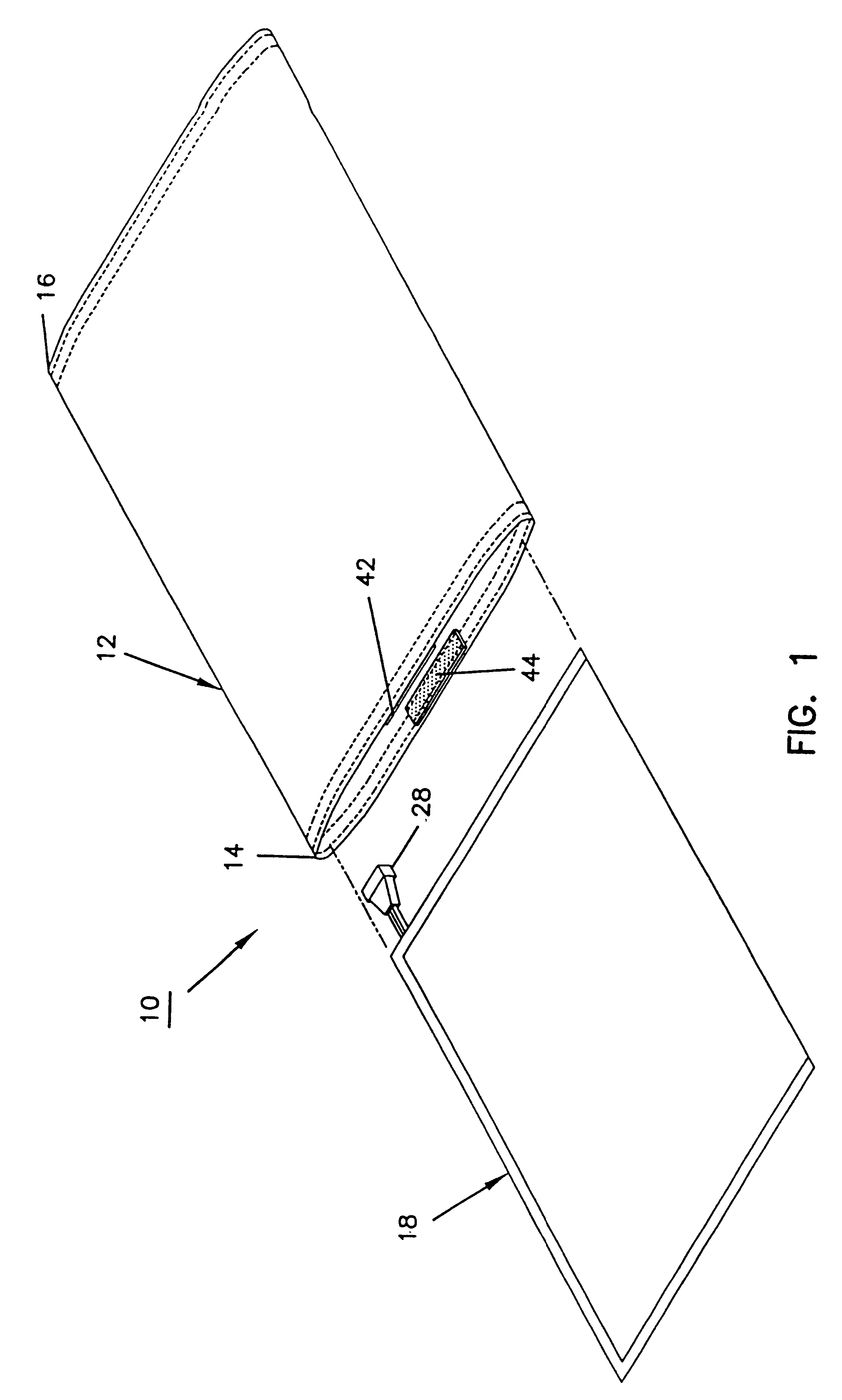
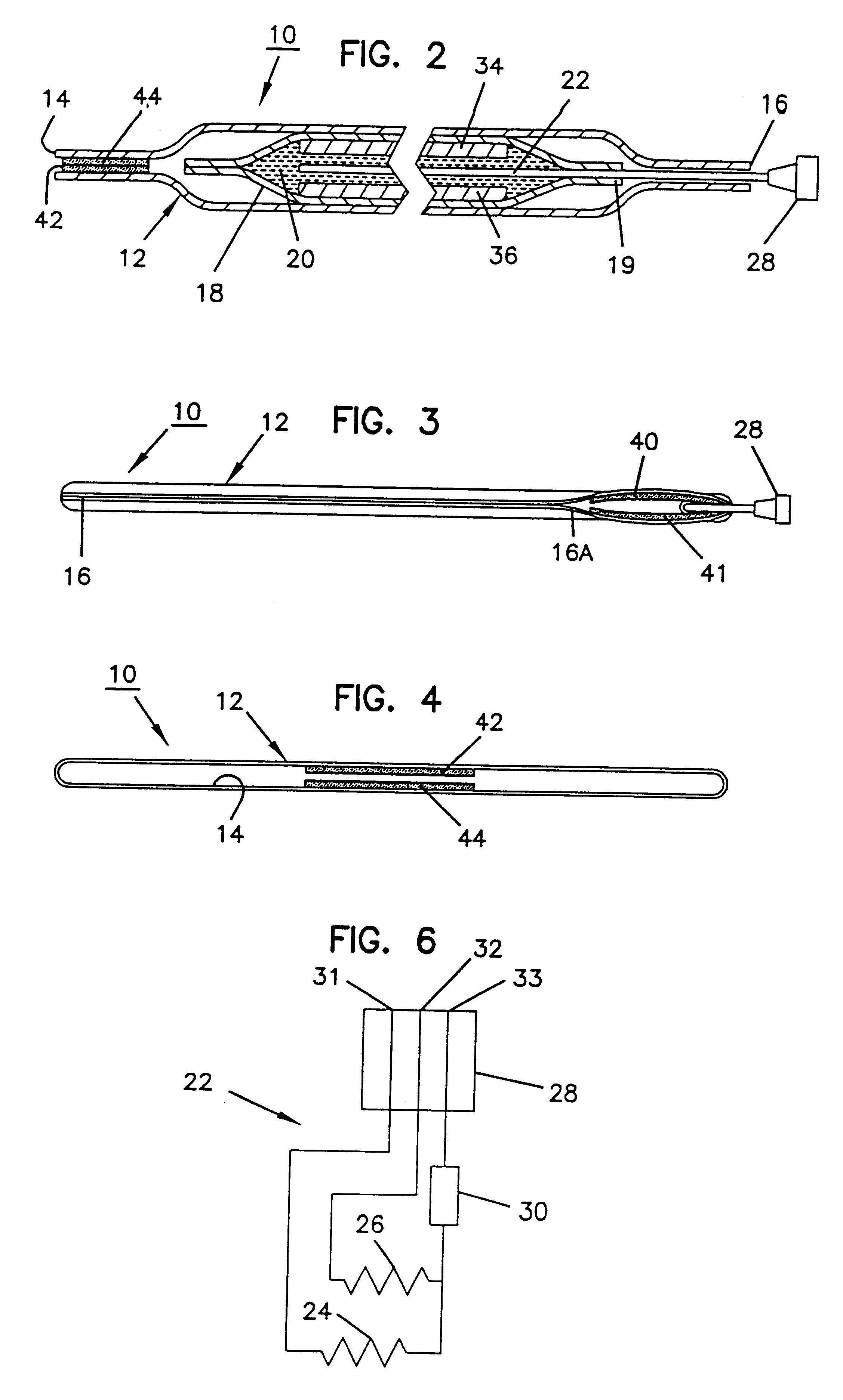
The heating pad 10 is substantially rectangular in shape. The pad 10 includes an outer cloth covering 12 which is open at its opposite ends 14, 16. Contained within cloth covering 12 is a sealed vinyl or plastic envelope 18. Envelope 18 is completely sealed to define an internal volume. Contained within the volume is an electric resistive element (FIGS. 2, 5 and 6) in the form of a plurality of wire coils 22.

The resistive element 22 in a preferred embodiment includes a first resistive coil 24 and a second resistive coil 26. The coils 24, 26 terminate at a coupling 28 which includes three female connectors 31, 32 and 33. Connector 31 and connector 33 are electrically connected to opposite ends of coil 24. Connector 32 and connector 33 are connected to opposite end of coil 26 as best shown schematically in FIG. 6. Each of coils 26, 24 are connected to connector 33 through a thermal switch 30 which will be more fully described. Also, as will be described, coil 24 is ...


PUM


Abstract

A heat retention device is disclosed in the form of a heating pad which includes an electrically resistive coil contained within a volume. The coil terminates at an electric coupler which is external of the volume. A heat retention mass is contained within the volume in thermal conductivity with the resistive element.

Description

II. BACKGROUND OF THE INVENTION1. Field of the InventionThis invention pertains to thermal retention devices for storing thermal energy and releasing the thermal energy over time. More particularly, this invention pertains to a thermal retention device which utilizes a phase change material as a medium for storing and releasing thermal energy.2. Description of the Prior ArtThe prior art includes so-called phase change materials for storing thermal energy. A phase change material is a material which includes a substance which changes phase (for example, from solid state to liquid state or from a liquid state to a gaseous state) upon the application of thermal energy to the material. The process of changing phase results in energy (referred to as latent heat) being stored in the material. When the phase change reverses, the latent heat is released.Phase change materials can be provided with a wide variety of phase change temperatures (i.e., the temperature at which the phase change ma...

Claims


Application Information

Patent Timeline
Patent Type & Authority Patents(United States)
IPC IPC(8): F28D20/02A61F7/00A61F7/02A61F7/03A61F7/08H05B3/34
CPCA61F7/007F28D20/028A61F2007/0292Y02E60/145Y02E60/14
Inventor HYATT, GARY F.
Owner PHASE CHANGE ENERGY SOLUTIONS INC
Learn More