Lighting device

a technology of light source and light source, which is applied in the direction of signalling/lighting device, light source support device, textiles and paper, etc., can solve the problems of mechanical operation, insufficient irradiation of some parts, and weak light effect at the bedside of a patient in a hospital sickroom

Inactive Publication Date: 2001-12-25
LABOSPHERE INST
View PDF3 Cites 7 Cited by
  • Summary
  • Abstract
  • Description
  • Claims
  • Application Information

AI Technical Summary

Problems solved by technology

Due to the location of the lighting device, the lighting effects at the bedside of a patient lain in a sickroom in hospital become comparatively weak.
However, for examining the conditions of a patient with such a flashlight, it is necessary that the examiner has a flashlight, which is capable of irradiating light to parts of interest, readily available at hand; for this reason, one hand is occupied by holding such a flas

Method used


Image

  • Lighting device
  • Lighting device
  • Lighting device

Examples


Embodiment Construction

Preferred embodiments of the present invention are described in the following, with occasional references being made to the attached drawings. The embodiments explained in the following do not cover the techniques of the present invention comprehensively, but exemplify embodiments to implement the present invention; thus, it is apparent for any person skilled in the art that a wide variety of variations and conversions, and amendments or deletions of the configuration are conceivable.

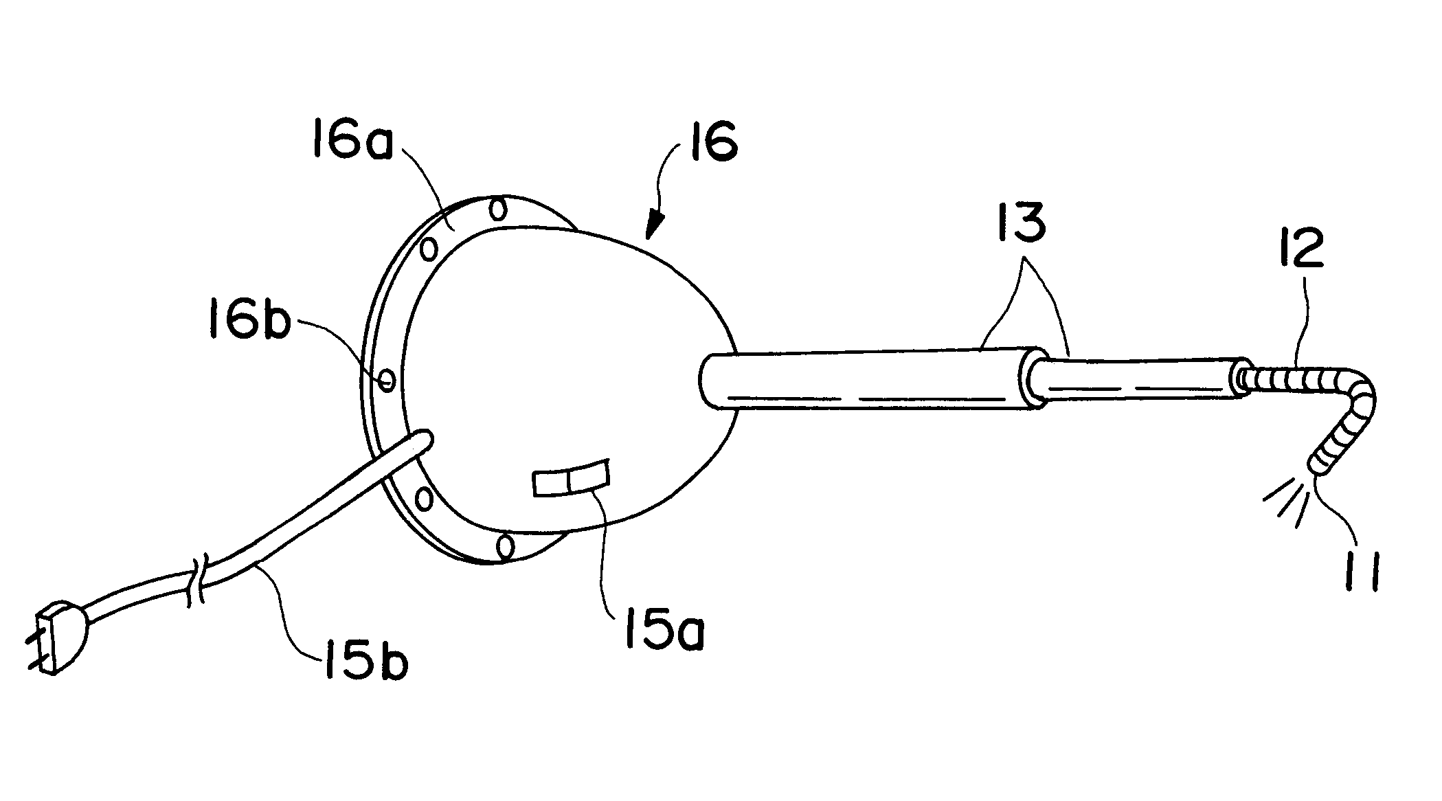
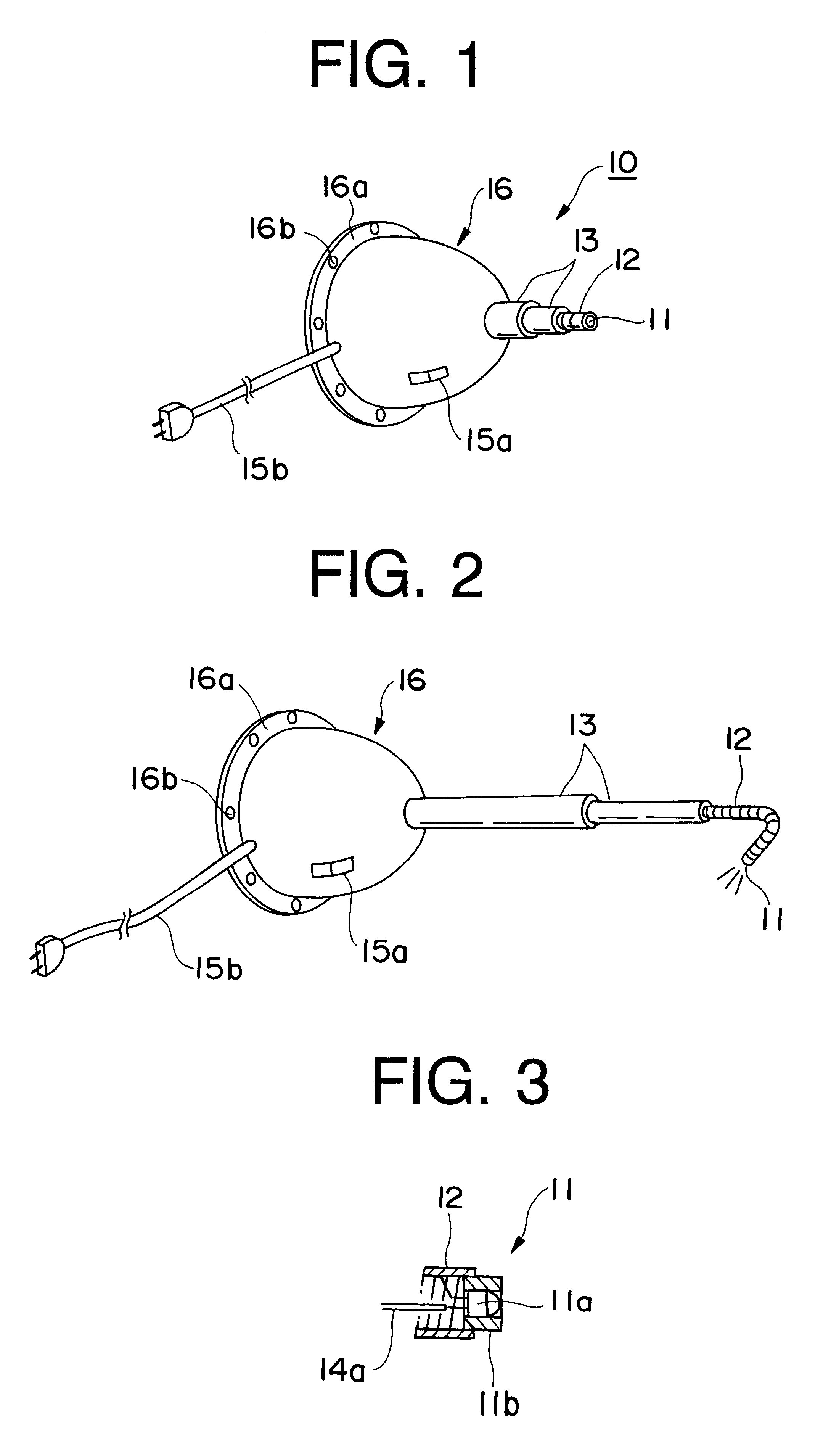
FIGS. 1 to 3 show the embodiment of a lighting device according to the present invention.

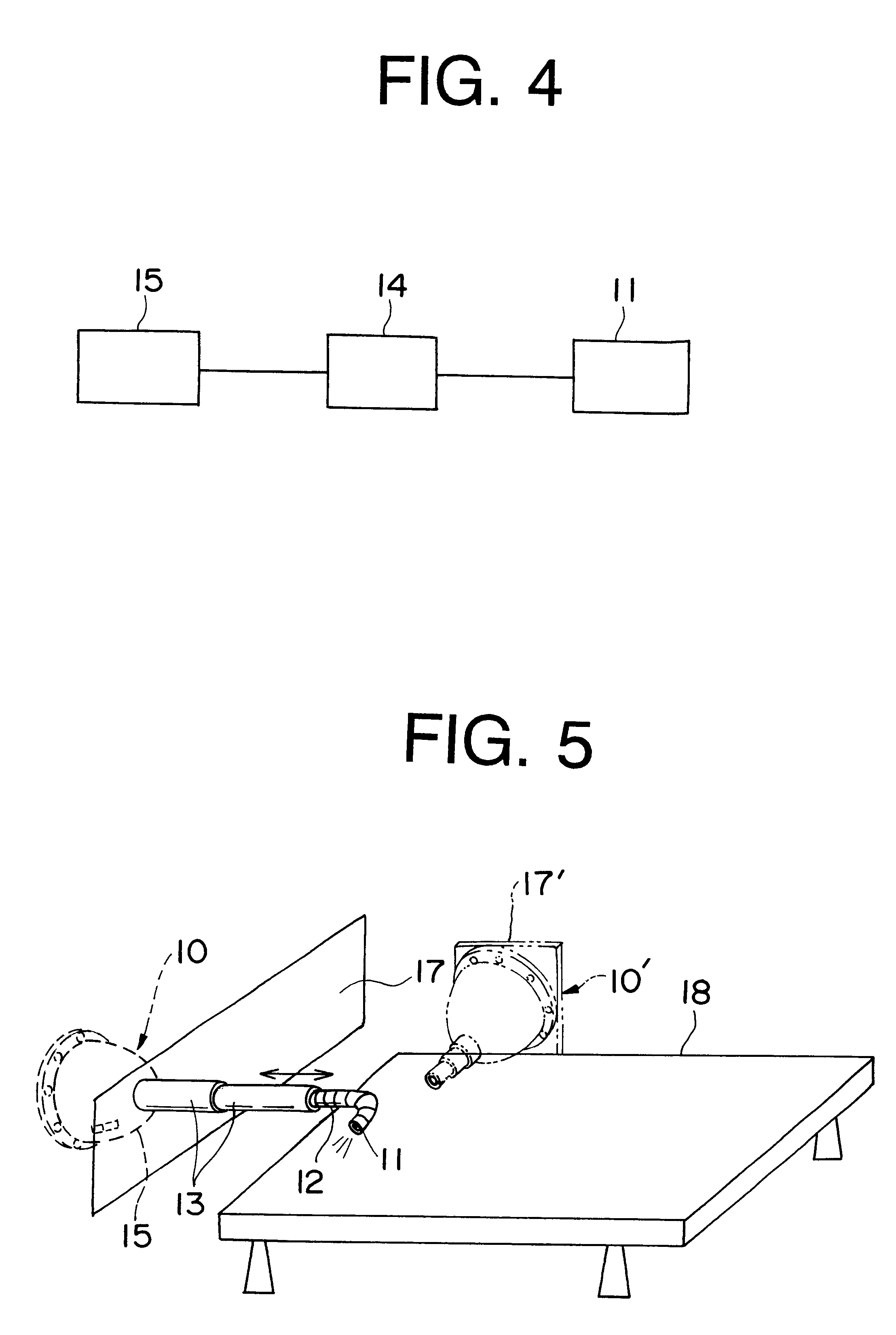
In FIGS. 1 and 2, an installation-type lighting device 10 comprises of a light irradiation portion 11, flexible shaft 12 that supports the light irradiation portion 11 at the tip, extendible portions 13 that support the flexible shaft 12 at the base, and a case 16 that supports the extendible portions 13. The case 16 as shown in FIG. 4, has a built-in drive portion 14 that drives the light irradiation portion, and a...


PUM

PropertyMeasurementUnit
Angleaaaaaaaaaa
Poweraaaaaaaaaa
Flexibilityaaaaaaaaaa

Abstract

A lighting device 10, having a light irradiation portion 11 comprised of light-emitting elements; a freely turnable flexible shaft 12; extendible portions 13 that support the said flexible shaft at the base, house the flexible shaft, and provide a nested housing for each one of the extendible portions within one another; a drive portion 14 that drives the light irradiation portion; a power supply portion 15 that supplies electric power to the drive portion; and a case 16 covering the drive portion at least, which more preferably covers the extendible portions, as well. Moreover, this includes ones having a spring mechanism that allows said extendible portions and said flexible shaft to freely extend, and by the spring mechanism, as the flexible shaft extends, said nested extendible portions can be extended in succession.

Description

The present invention relates to a lighting device that is made capable of irradiating light arbitrarily to a desired place.BACKGROUND TECHNOLOGIESConventionally, so-called indoor light, such as fluorescence light, incandescent light, etc., which is installed on a ceiling surface has been used as a lighting device, for example in sickrooms in hospitals, etc. Due to the location of the lighting device, the lighting effects at the bedside of a patient lain in a sickroom in hospital become comparatively weak. Therefore, even when the indoor light is turned on, in order to examine the conditions of a patient in an accurate and detailed manner, it is required to use a flashlight such as a penlight, etc. to pinpoint parts of interest, in addition to the indoor light.However, for examining the conditions of a patient with such a flashlight, it is necessary that the examiner has a flashlight, which is capable of irradiating light to parts of interest, readily available at hand; for this rea...

Claims


Application Information

Patent Timeline
IPC IPC(8): F21V21/14F21V21/30F21V21/32F21V21/22F21L14/00F21S2/00F21V8/00F21V11/18F21V14/08F21V15/01F21W131/20F21Y101/02H01L33/48
CPCF21V21/145F21V21/22F21V21/30F21V21/32G02B6/0008
Inventor TAMAOKI, KEIKOMINATO, KIYOTAKATAMAOKI, SATOSHI
Owner LABOSPHERE INST
Why Eureka
Try Eureka