

Snap in cable connector
- Summary
- Abstract
- Description
- Claims
- Application Information
AI Technical Summary
Benefits of technology
Problems solved by technology
Method used
Image

Examples
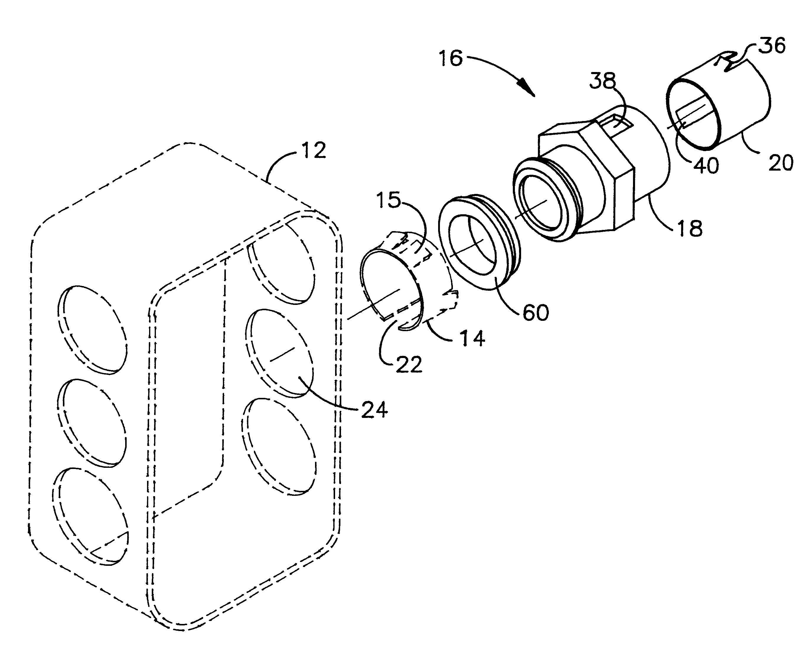
first embodiment
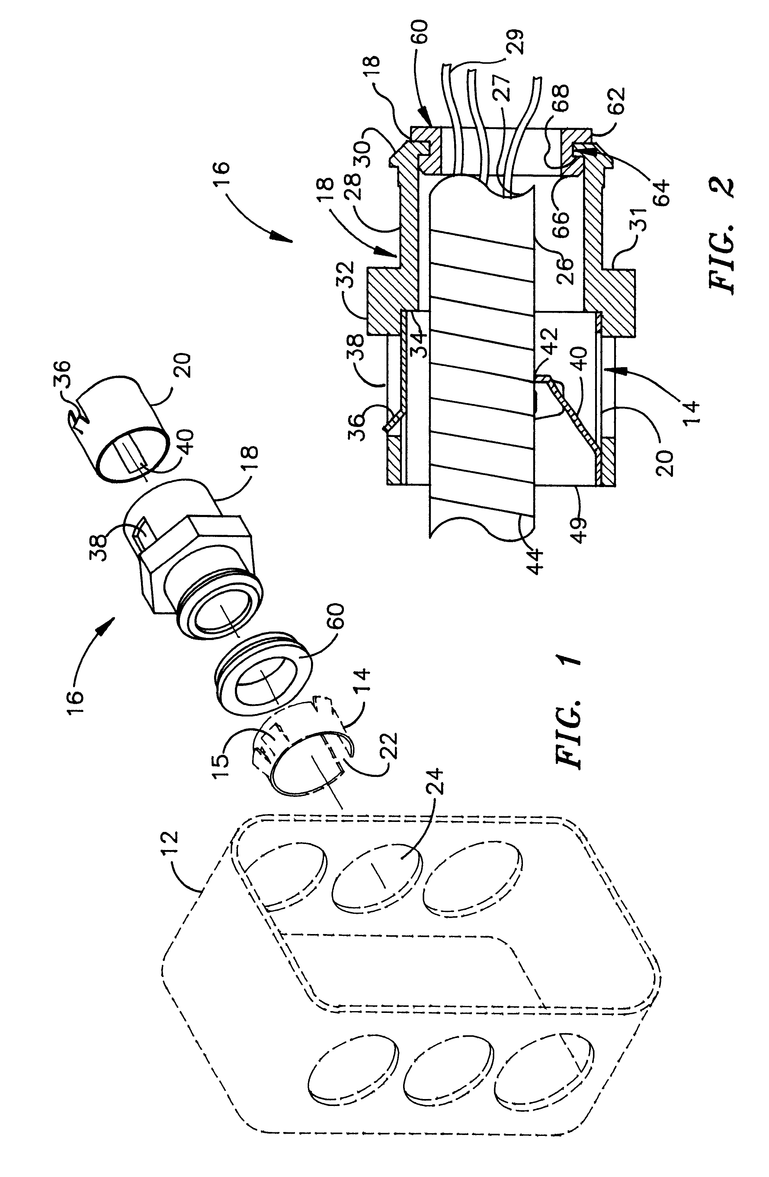
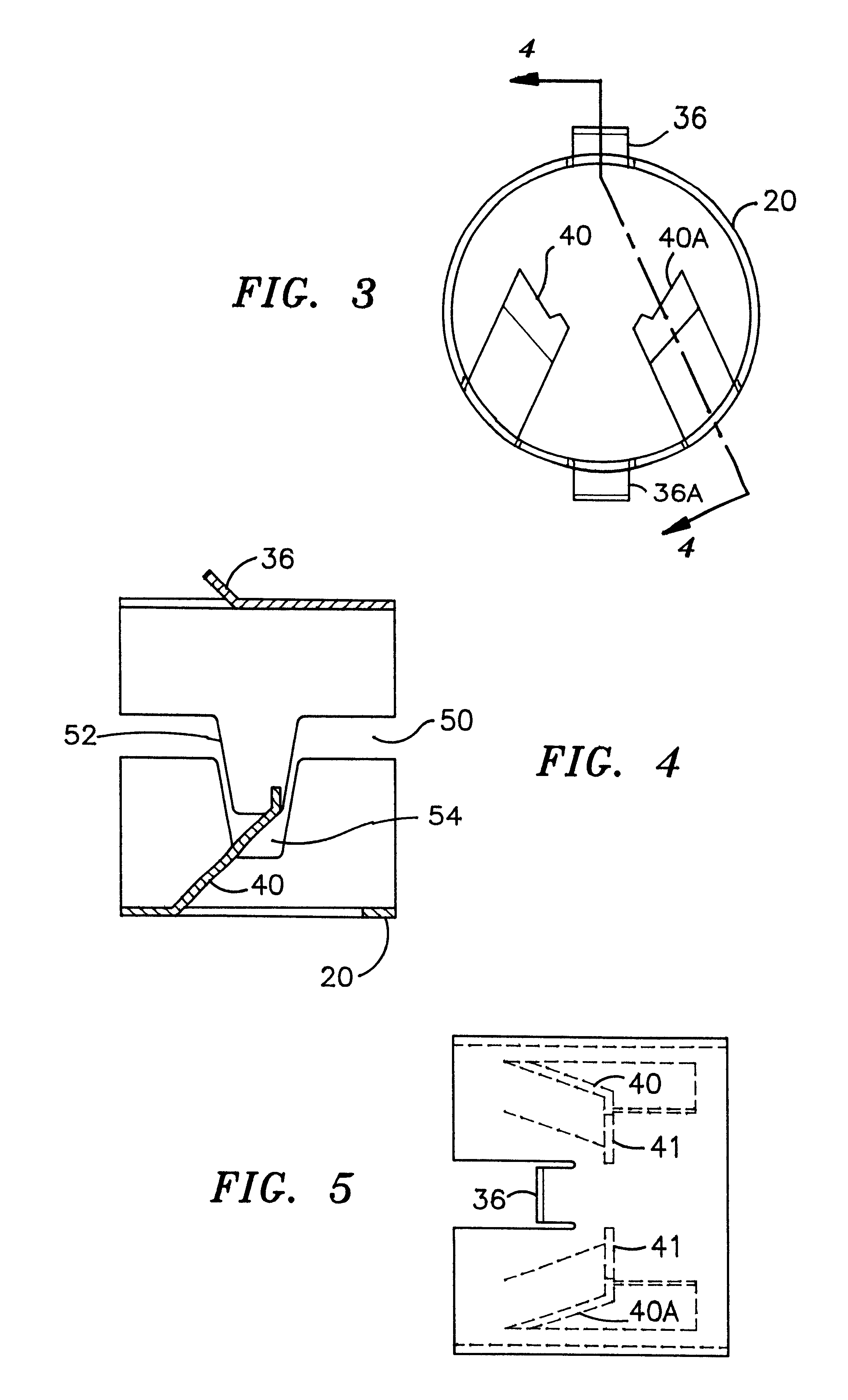
a steel locking ring 20 is illustrated as inserted into die cast member 18 with a first tang 36 in a corresponding opening 38 in die cast member 18. As is seen, the spring steel tang 36 has an outward extending angle which permits the tang to be depressed inward as the steel locking ring is inserted into the outer aperture 49 of the member 18, yet spring outward into openings 38 and 38A to prevent withdrawal. Also illustrated is cable tang 40 in steel locking ring 20, gripping the bottom of the helical recesses of armored cable 26 at point 42 in helical groove 44. Shoulder 34 of die cast member 18 is positioned such that the end of tang barely clears the end of opening 38 before steel locking ring 20 reaches a place where it cannot be inserted further.
As is seen in FIG. 2, the armored cable 26 is cut at the end 27 of the connector which is just inside the inner end. The wires 29 are connected on the inside of the junction box. Also shown in FIG. 2 is a plastic grommet 60 which has f...
PUM
 Abstract
Description
Claims
Application Information