Continuously variable transmission

a transmission and variable technology, applied in the direction of gearing elements, belts/chains/gearrings, portability lifting, etc., can solve the problems of reducing the space requirements and affecting the operation of the torque sensor

Inactive Publication Date: 2002-01-08
LUK GETRIEBE SYST
View PDF11 Cites 89 Cited by
  • Summary
  • Abstract
  • Description
  • Claims
  • Application Information

AI Technical Summary

Benefits of technology

An object of the instant invention is to provide a continuously variable transmission which is designed in such a way that its ratio can be changed within short intervals of time.
Another object of the invention is to provide a relatively simple, compact and inexpensive continuously variable transmission which can be utilized as a superior substitute for the aforedescribed conventional continuously variable transmissions.
An additional object of the invention is to provide novel and improved means for moving the axially movable flanges relative to axially fixed flanges of pulleys on the input and output shafts of a continuously variable transmission, particularly a transmission which can be utilized in the power train of a motor vehicle and can receive torque from the output element (such as a crankshaft or a camshaft) of an internal combustion engine or another prime mover.
The second flange of the pulley can be provided with a control edge (e.g., defined by a circumferentially complete internal annular shoulder) which is adjacent the shaft. The hydraulic motor of the means for moving the second flange relative to the input shaft toward and away from the first flange includes the aforementioned at least one additional or third plenum chamber for a supply of pressurized fluid, and the means for connecting the first and / or second plenum chamber with the third plenum chamber can comprise at least one passage (e.g., a bore) provided in the input shaft and having an open end adjacent the control edge so that the latter can regulate the rate of fluid flow in the at least one passage in response to axial movement of the second flange relative to the shaft.

Problems solved by technology

However, the utilization of such third plenum chambers results in considerable pumping losses because of uninterrupted flow of pressurized fluid from the first plenum chambers.
However, the just described torque sensor also exhibits certain drawbacks.
For example, the space requirements of the torque sensor, as seen in the axial direction of the input shaft, are rather pronounced which is evidently undesirable in many types of motor vehicles.
Moreover the torque sensor is quite complex and comprises a rather substantial number of component parts.

Method used


Image

  • Continuously variable transmission
  • Continuously variable transmission
  • Continuously variable transmission

Examples


Embodiment Construction

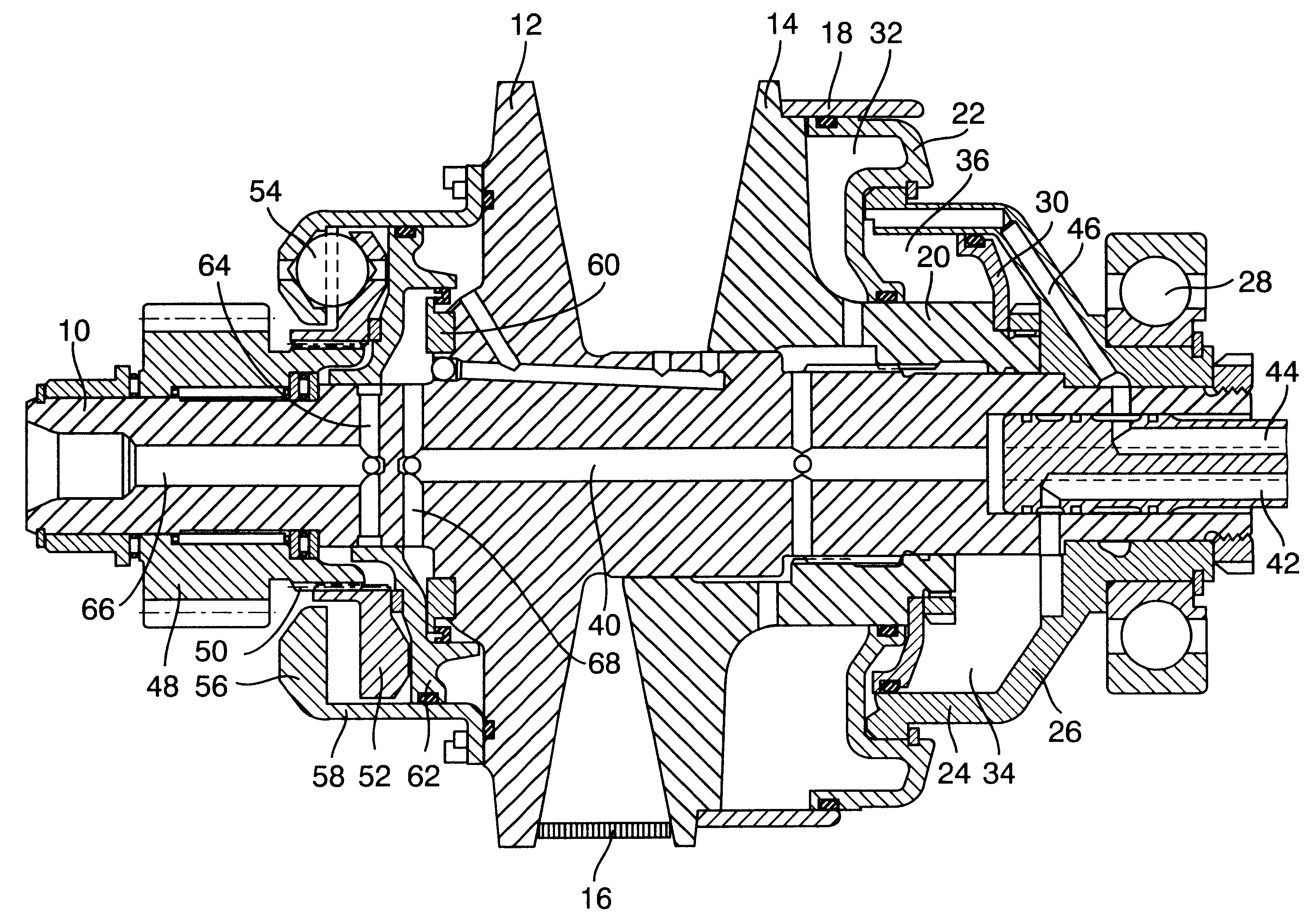
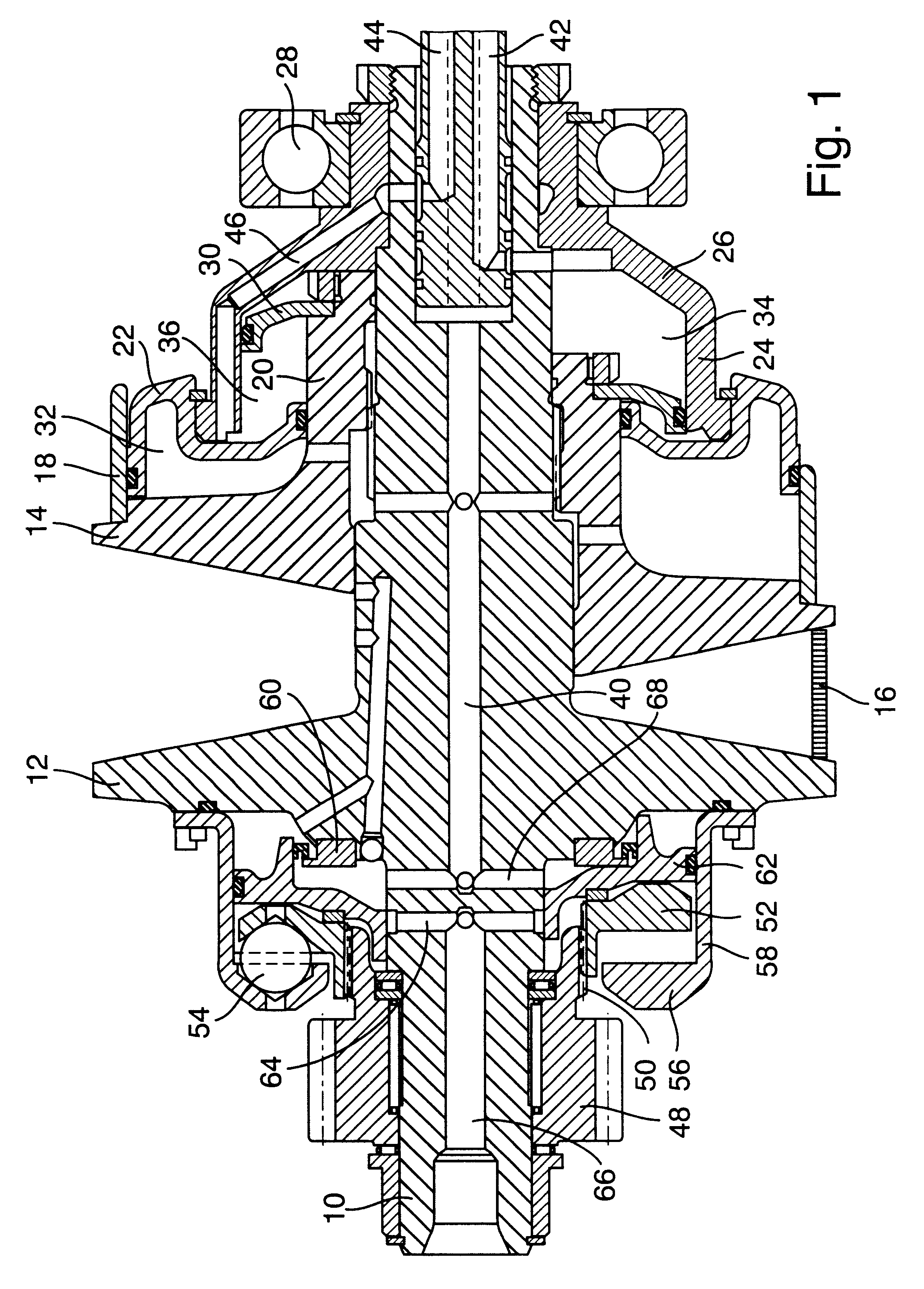
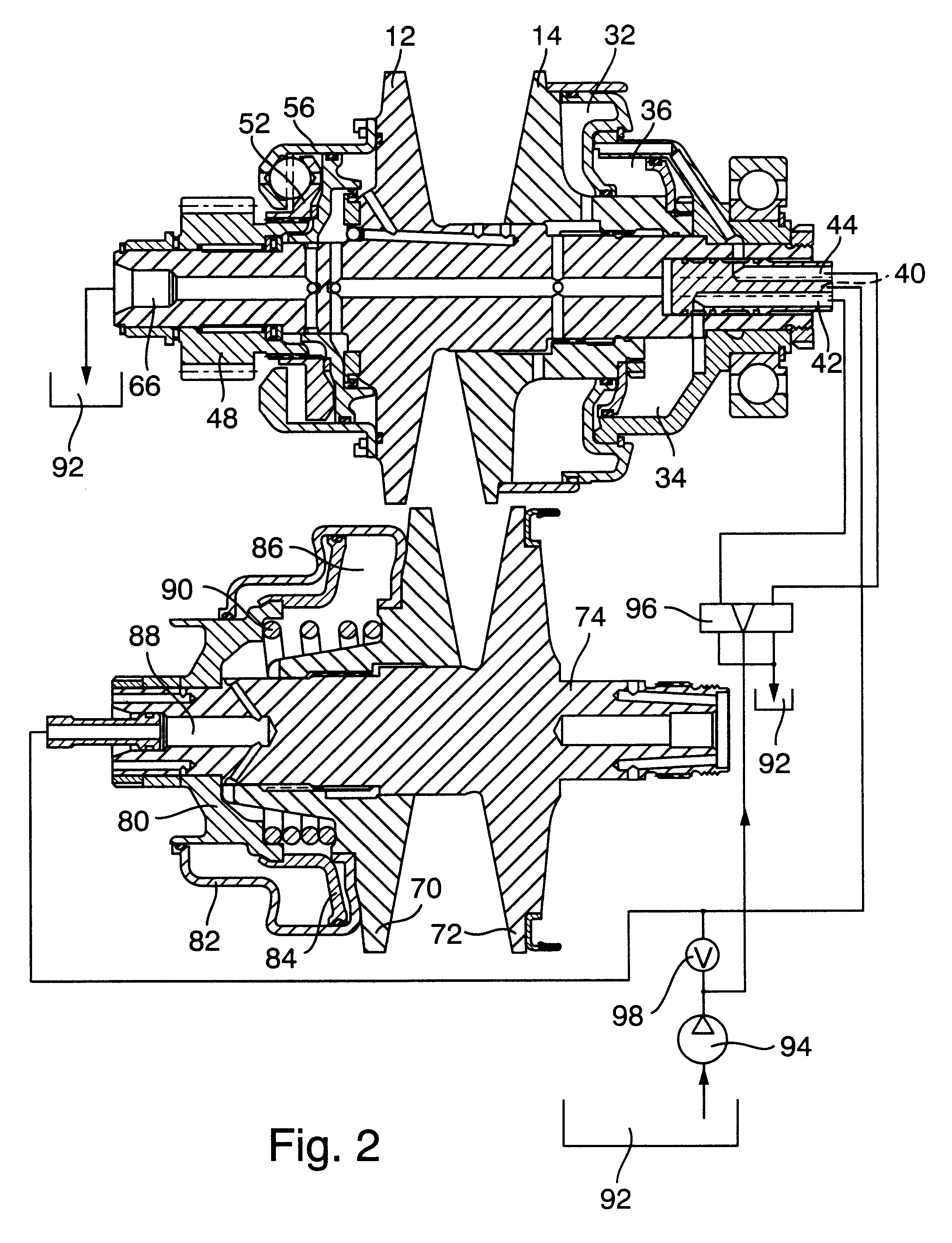
FIGS. 1 and 2 show a continuously variable transmission (CVT) which comprises an input shaft 10 adapted to be driven by a suitable prime mover, such as by the output shaft of a combustion engine in the power train of a motor vehicle. The input shaft 10 carries a first adjustable pulley or sheave including a first flange 12 which is or which can be of one piece with the shaft 10, and a second flange 14 which is non-rotatably but axially movably carried by the shaft 10. The upper half of FIG. 1 shows the flange 14 in a position at a maximum axial distance from the flange 12, and the lower half of FIG. 1 shows the flange 14 in a position at a minimum axial distance from the flange 12.

An endless flexible element 16 (such as a chain or belt and hereinafter called chain for short) is trained over the pulley including the flanges 12, 14 in such a way that its marginal surfaces abut against the adjacent radially outwardly flaring conical surfaces of these flanges. That portion of the chain ...


PUM


Abstract

A continuously variable transmission for use in the power train of a motor vehicle has parallel input and output shafts, an adjustable pulley on each shaft, an endless torque transmitting chain or belt trained over the pulleys, and a torque sensor which transmits variable torque from the engine of the motor vehicle to the pulley on the input shaft. The torque sensor also serves to initiate and regulate the adjustments of the pulleys.

Description

The invention relates to continuously variable transmissions (CVT) of the type employing rotary input and output shafts, adjustable pulleys on the shafts, and an endless flexible element (such as an endless flexible chain or belt and hereinafter called chain for short) which is trained over the pulleys. Transmissions of such character are preferred by numerous makers of motor vehicles or power trains for use in motor vehicles because they exhibit important advantages over other types of continuously variable transmissions, e.g., those which employ planetary gears. Thus, the ride in a motor vehicle comprising a power train embodying a continuously variable transmission which comprises input and output shafts with adjustable pulleys and an endless chain trained over the pulleys is more comfortable to the operator and other occupants of the motor vehicle, and the engine can be operated with considerable savings in fuel consumption.Published German patent application Serial No. 195 44 6...

Claims


Application Information

Patent Timeline
Patent Type & Authority Patents(United States)
IPC IPC(8): F16H55/56F16H55/32F16H61/66F16H63/02F16H63/06F16H61/662F16H9/18
CPCF16H55/56F16H63/065F16H61/66272F16H61/662
Inventor EHRLICH, MATTHIASWALTER, BERNHARD
Owner LUK GETRIEBE SYST
Why Eureka
Try Eureka