Expandable stinger planter

a planter and expandable technology, applied in the direction of planting, mechanical machines/dredgers, transplanting, etc., can solve the problems of destroying the surrounding area, compromising the surrounding habitat, and long time-consuming and labor-intensive process of planting vegetation in rough terrain

Inactive Publication Date: 2002-01-29
DANIEL A CULLEY +1
View PDF14 Cites 20 Cited by
  • Summary
  • Abstract
  • Description
  • Claims
  • Application Information

AI Technical Summary

Benefits of technology

In another aspect of the invention (exemplified by FIGS. 19-21), the expandable stinger planter 10 is provided for attachment to an excavator type boom 14. The stinger planter 10 includes a base frame 20 which is configured to be secured to the excavator type boom 14, and a pivot frame 24 mounted to the base frame 20. The pivot frame 24 defines first and second pivot axes X and Y that are approximately perpendicular to one another. The stinger 34 is comprised of a pair of elongated probes 36 secured together for relative pivotal movement about a probe axis P that is transverse to the probes 36. The probes 36 include upper ends 38 that are disposed above the probe axis P. Bottom ends 40 are disposed below the probe axis P. A stinger mounting frame, including a linkage 74 is mounted to the pivot frame 24 at the second pivot axis Y and suspends the stinger 34 from the pivot frame 24 for movement about the first and second axes X, Y. The linkage 74 includes paired four bar links 78, each with four pivots. One pivot 80 is coaxial with the second pivot axis Y. Two pivots 81, 82 are connected at upper ends of the probes, and a remaining pivot 83 is situated between the two pivots 81, 82. An actuator 60 which includes a ram cylinder 63 is mounted between opposed pivots on the linkage such that extension and retraction of the ram cylinder 63 will result in pivotal motion of the probes 36 about the probe axis P between an open position wherein bottom ends 40 of the probes 36 are pivoted away from one another to form a plant discharge opening 42, and a closed position wherein the bottom ends 40 of the probes 36 are pivoted toward one another. The probes 36 form an upwardly open internal plant receiving receptacle 44 that is open to the plant discharge opening 42 at the open position whereby a plant placed in the plant receiving receptacle 44 may be discharged through the ...

Problems solved by technology

Planting of vegetation in rough terrain has long been a difficult and tedious process.
In fact, most planting done on steep embankments or rocky terrain has been accomplished by hand, because mechanized planters are often not capable of negotiating the terrain.
Further, bulky planting machinery can damage the surrounding area and seriously compromise the surrounding habitat.
Hand planting in steep, rocky, or otherwise rough terrain is often not successful because the conditions do not permit the planter to dig deep enough to secure the plants.
Also riparian areas are typically difficult to plant because the plant stock cannot be secured deeply in the embankment to prevent high water from washing the plants away.
Still, it is difficult and sometimes seemingly impossible to successfully plant such areas.
Shallow rooted whips of willow, cottonwoo...

Method used


Image

  • Expandable stinger planter
  • Expandable stinger planter
  • Expandable stinger planter

Examples


Embodiment Construction

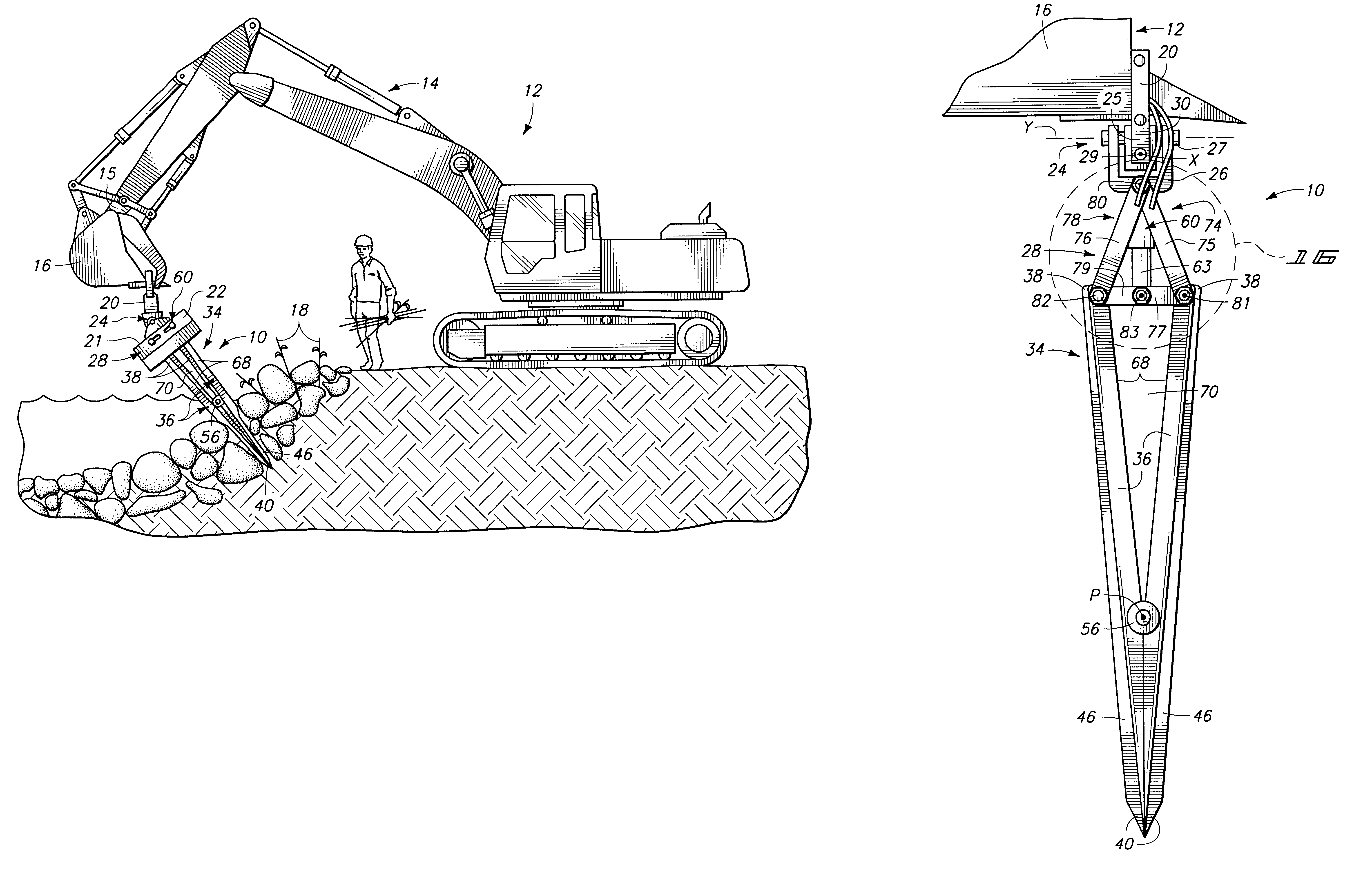
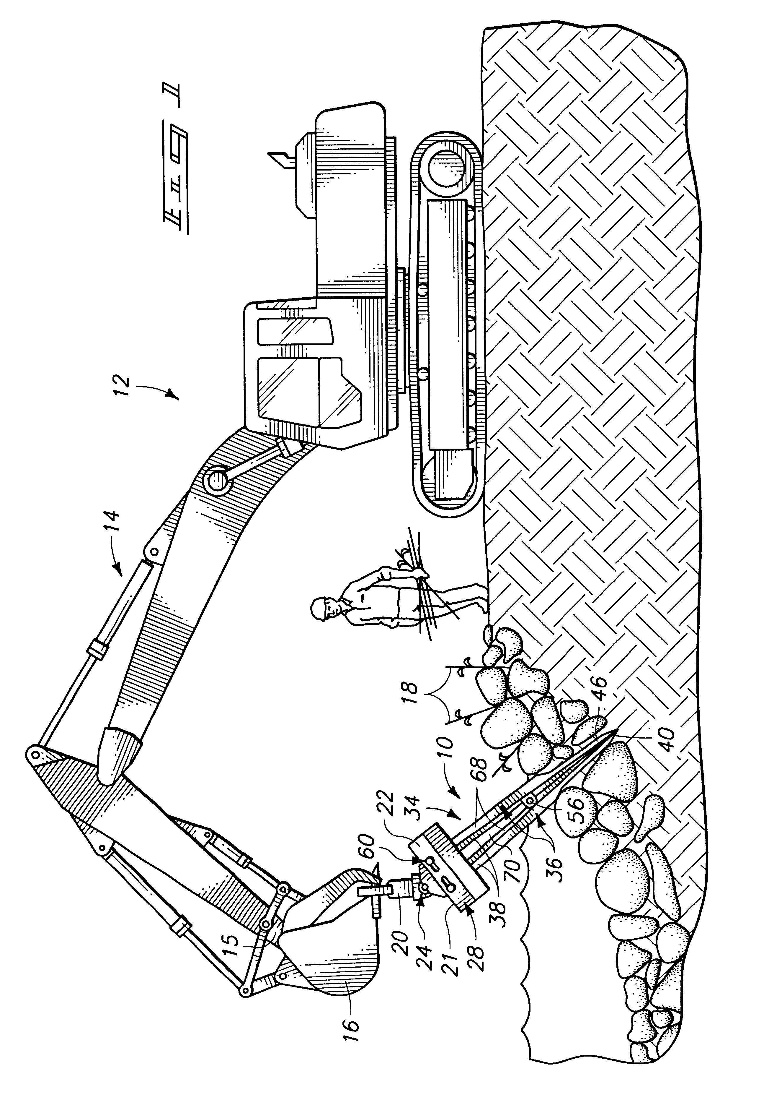
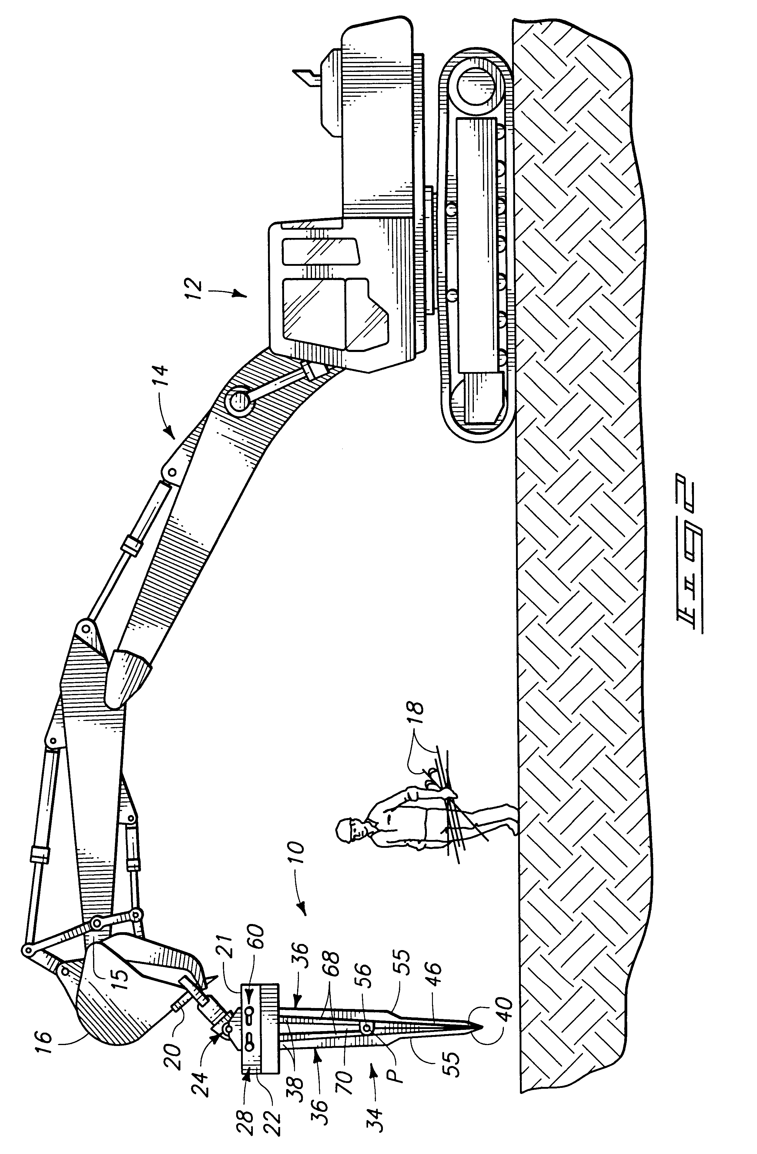
In preferred embodiments, the base frame 20 is configured to be secured to an excavator type boom 14. It is noted that the base frame 20 may be provided in alternate forms to facilitate mounting to various forms of booms, buckets, or other boom end hardware on a conventional excavator or related machine. The base frame 20 may be releasably attached to the boom 14 or bucket 16 using conventional fasteners such as bolts, clamps, or other fasteners well known in the fastening art as will be readily realized by those of ordinary skill in the art.

In preferred forms, the pivot frame 24 is mounted to the base frame 20. It is advantageous that the pivot frame 24 include a form of ball joint type joint (FIG. 4), forms of universal joints (FIGS. 14 and 20), or other pivot link arrangement that will permit relatively free pivotal movement of the planter 10 about multiple axes below the base frame 20. It is preferable that the pivot frame 24 allow the planter 10 to pivot about at least two angu...


PUM


Abstract

An expandable stinger planter is described which includes a base frame and a pivot frame mounted to the base frame for pivotal movement thereon about multiple pivot axes. A stinger comprised of a pair of elongated probes is mounted to the pivot frame and extending to bottom ends. A stinger mounting frame is operatively positioned between the pivot frame and at least one of the elongated probes. An actuator on the stinger mounting frame is operable to shift the bottom ends between a closed position and an open wherein the bottom ends are opened and form a plant discharge opening. An internal plant receiving receptacle within the probes is open to the plant discharge opening at the open position whereby a plant placed in the plant receiving receptacle may be discharged through the plant discharge opening.

Description

The present invention relates to planting and more particularly to apparatus for performing planting operations.Planting of vegetation in rough terrain has long been a difficult and tedious process. In fact, most planting done on steep embankments or rocky terrain has been accomplished by hand, because mechanized planters are often not capable of negotiating the terrain. Further, bulky planting machinery can damage the surrounding area and seriously compromise the surrounding habitat.Hand planting in steep, rocky, or otherwise rough terrain is often not successful because the conditions do not permit the planter to dig deep enough to secure the plants. Also riparian areas are typically difficult to plant because the plant stock cannot be secured deeply in the embankment to prevent high water from washing the plants away.Re-planting vegetation along riparian ways that have been denuded by flooding is ecologically desirable, not only to bolster the shorelines against erosion, but also...

Claims


Application Information

Patent Timeline
IPC IPC(8): A01B13/00A01C5/00A01C11/00A01C5/04A01G23/04A01G23/00
CPCA01B13/00A01C5/04A01G23/04A01C11/00Y10S414/125
Inventor CULLEY, DANIEL A.
Owner DANIEL A CULLEY
Why Eureka
Try Eureka