Method and apparatus for maintaining control of liquid flow in a vibratory atomizing device

a vibratory atomizing device and liquid flow technology, applied in lighting and heating apparatus, combustion types, dental surgery, etc., can solve the problems of damping the pumping action, not all of the liquid which is pumped through the perforations of the orifice plate becomes ejected from the upper surface of the plate, and reduces the output of atomized liquid particles

Inactive Publication Date: 2002-01-29
SC JOHNSON & SON INC
View PDF18 Cites 215 Cited by
  • Summary
  • Abstract
  • Description
  • Claims
  • Application Information

AI Technical Summary

Problems solved by technology

A problem occurs in these piezoelectric vibratory atomizer devices in that not all of the liquid which is pumped through the perforations in the orifice plate becomes ejected from the upper surface of the plate.
The liquid which is not ejected or ejected liquid which falls back on the plate remains on the upper surface of the plate and interferes with the atomizing action.
Eventually this accumulated liquid builds up to a degree such that it damps the pumping action and decreases the output of atomized liquid particles.
However, these nozzle plates neither vibrate nor do they convert radial actuator movements to up and down vibratory movements of a perforated orifice plate.
Moreover, a wick is not used to transfer liquid to these nozzle plates.
This nonejected liquid or liquid which has fallen back on the plate tends to saturate the upper end of the liquid conductor element such that it diminishes the ability of the element to draw additional liquid from the reservoir.
The returned liquid which is directed by the liquid conductor element tends to increase the saturation of the element and thereby restricts the element's ability to supply additional liquid from the reservoir, at least until the returned liquid has been re-atomized.

Method used


Image

  • Method and apparatus for maintaining control of liquid flow in a vibratory atomizing device
  • Method and apparatus for maintaining control of liquid flow in a vibratory atomizing device

Examples


Embodiment Construction

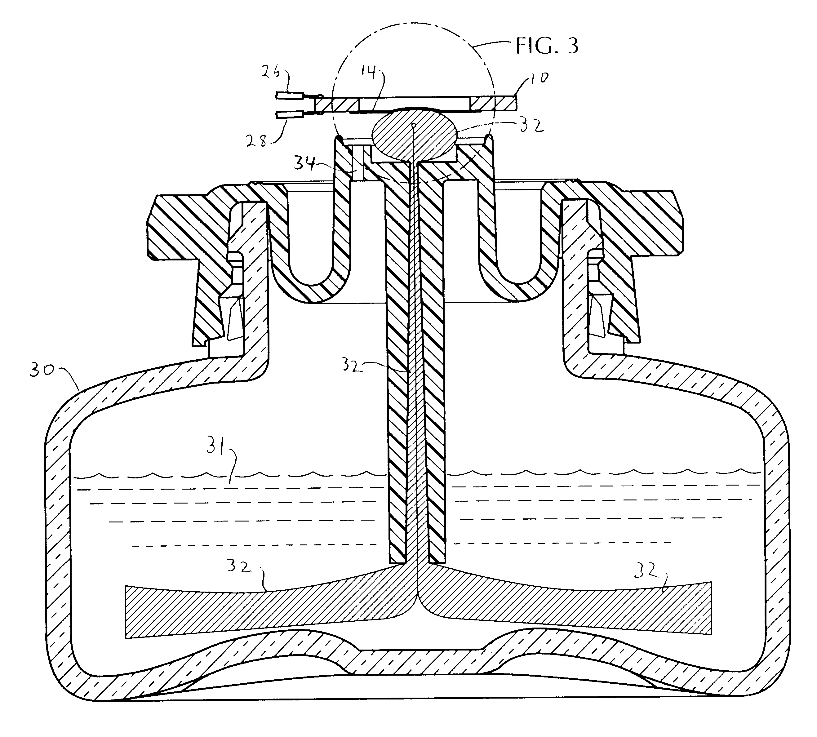
The vibratory atomizing device of FIG. 1 comprises an annularly shaped piezoelectric actuator element 10 having an inner diameter center hole 12 and an orifice plate 14 which extends across the inner diameter hole 12 on the underside of the actuator and slightly overlaps an inner region 15 of the actuator. The orifice plate 14 is fixed to the underside of the actuator 10 in the overlap region 15. Any suitable cementing means may be used to fix the orifice plate 14 to the piezoelectric actuator element 10; however, in cases where the device may be used to atomize liquids which are corrosive, or aggressive in that they tend to soften certain cements, it is preferred that the orifice plate be soldered to the piezoelectric element. Also, the outer diameter of the orifice plate 14 may be as large as the outer diameter of the actuator element 10 so that it extends over the entire surface of one side of the actuator element. It should be understood that this invention also includes a const...


PUM


Abstract

Liquid to be atomized is supplied from a wick to the underside of a vibrating orifice plate which pumps the liquid up through atomizing orifices in the plate and ejects the liquid from is upper side; and liquid which is pumped up through the orifices in an elevated region of the plate, but which has not been ejected, is directed back down through larger openings in a lower region of the plate. The liquid also flows back onto the wick which places the liquid in capillary communication along the underside of the plate with the atomizing orifices for reputing and ejection.

Description

1. Field of the InventionThis invention relates to the atomization of liquids by means of a vibrating perforated member, such as a membrane or an orifice plate. More particularly the invention concerns the control of liquid flow through such orifice plate to ensure a stable and continuous atomizing operation.2. Description of the Related ArtVibratory atomizing devices are well known, as seen for example, in U.S. Pat. No. 5,152,456, U.S. Pat. No. 5,164,740, U.S. Pat. No. 4,632,3171 and U.S. Pat. No. 4,533,082. In general, such devices incorporate a thin plate having at least one small orifice extending therethrough and which is attached to and vibrated by a piezoelectric actuation element. An alternating voltage applied to the piezoelectric actuation element causes it to expand and contract; and this expansion and contraction produces up and down vibratory movement of the orifice plate. A liquid supply, such as a wick, transports liquid to be atomized from a reservoir to the one side...

Claims


Application Information

Patent Timeline
Patent Type & Authority Patents(United States)
IPC IPC(8): B05B17/04B05B17/06B05B17/00
CPCB05B17/0684B05B17/0646B05B17/06
Inventor MARTIN, FREDERICK H.HELF, THOMAS A.SCHRAM, DAVID J.JASHINSKE, MARYANNTOMKINS, DAVID A.MARTENS, III, EDWARD J.
Owner SC JOHNSON & SON INC
Why Eureka
Try Eureka