Dental light controller and concentrator

a concentrator and light controller technology, applied in the field of dental instruments, can solve the problems of reducing the intensity and effectiveness of the beam of the dentist's eye, damage to the surface form, and affecting the effect of the beam intensity

Inactive Publication Date: 2002-02-12
DUNAWAY DARCY M
View PDF17 Cites 42 Cited by
  • Summary
  • Abstract
  • Description
  • Claims
  • Application Information

AI Technical Summary

Problems solved by technology

However, reflections of such bright light from a mouth often reach the dentist's eyes where they are intense enough to be irritating.
Also, if a polymerizing light is held too far from the restorative the intensity and effectiveness of its beam will decrease.
Further, the light wand should not be close enough to contact the restorative since contact from a wand assembly will damage the surface form of the restoration.
Available shields exhibit detrimental features.
Many shields are designed as cones or parabolic forms which are cumbersome because they require more space and weight.
Thus they tend to contact the restorative composition which is likely to cause damage.
This shield provides a see-through segment with reduced intensities and filtration of blue light for safe viewing of the treatment field but others do not enable adequate monitoring of the treatment field.
Its conical reflective surface will direct light in arbitrary, unfocused patterns and it is made of opaque polymers which do not provide an adequate view treatment field.
It is formed of a copolymer of ethylene and vinyl acetate which will not provide an adequate view of the treatment field.
However, it is cumbersome and difficult to control the wand and tissues and also hold the paddle.
It is made of orange plastic as a light filter, but is awkward and does not adequately collect or redirect reflected light.
Because of its limited dimensions, such a mirror will modify some, but neither all nor most of the light reflected.
Additionally, operators have used eyeglass covers and pigmented eyeglass lenses to protect their eyes, but such covers and lenses will not adequately reflect the reflected light.

Method used


Image

  • Dental light controller and concentrator
  • Dental light controller and concentrator
  • Dental light controller and concentrator

Examples


embodiment-- application

PREFERRED EMBODIMENT--APPLICATION

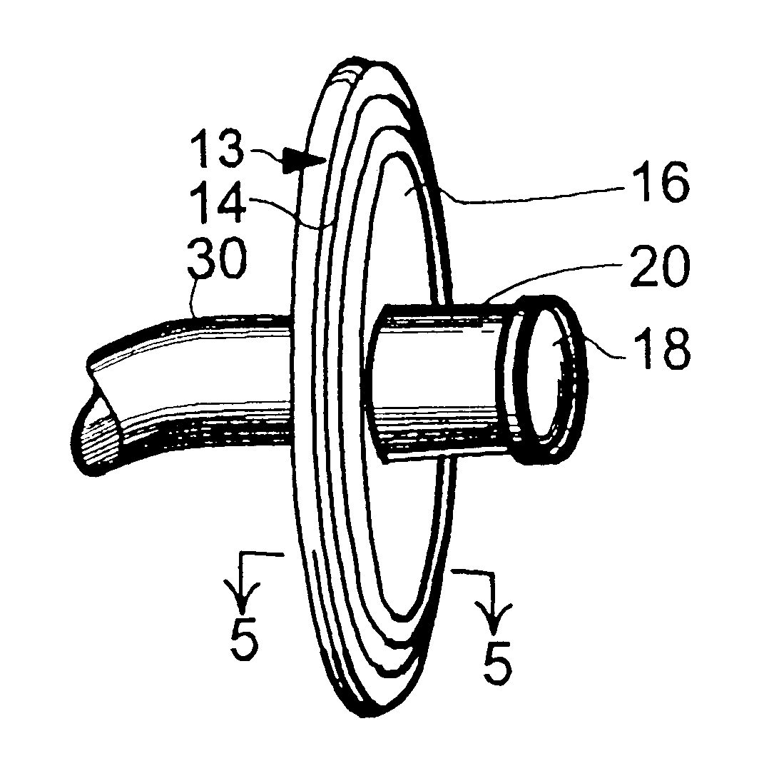
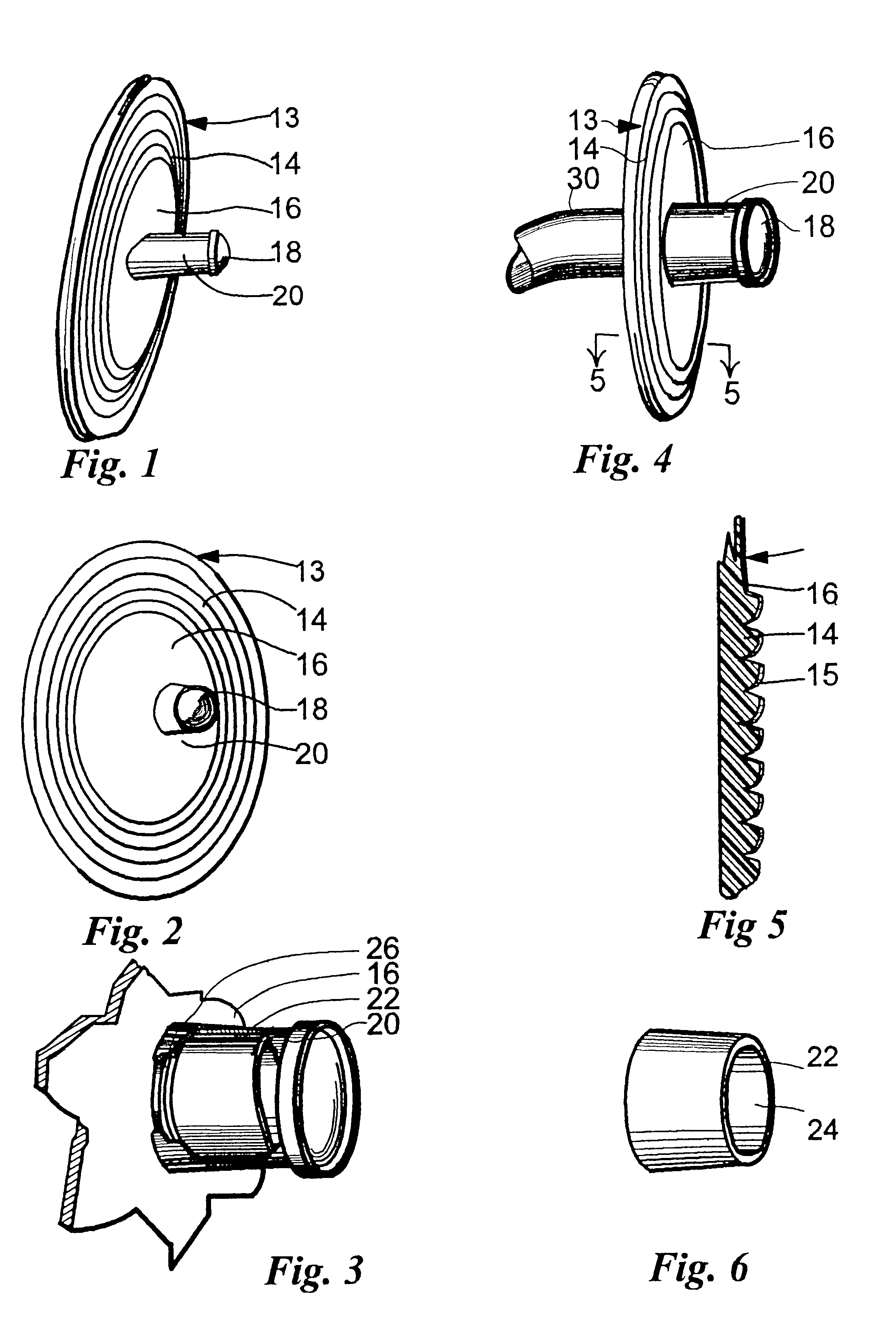
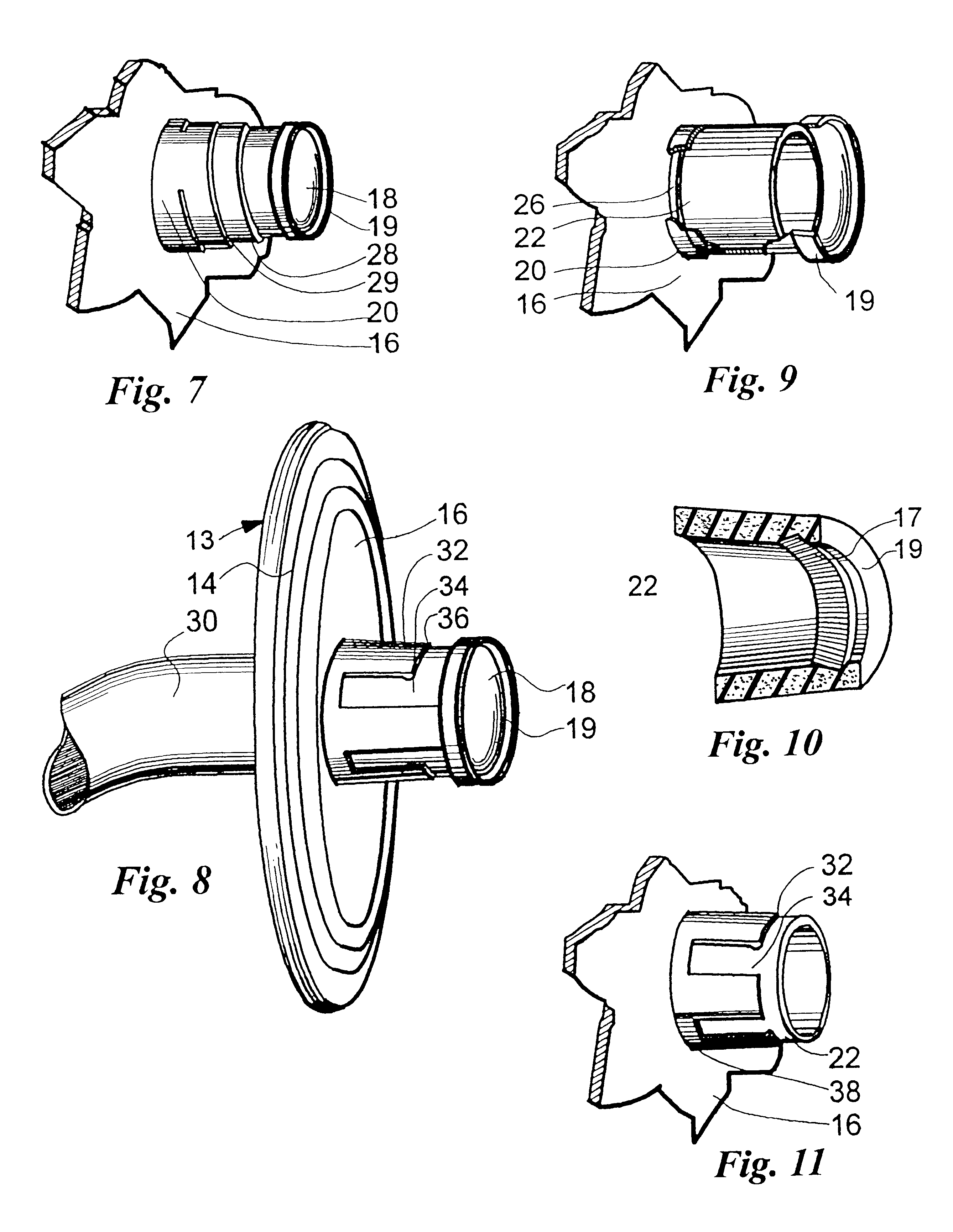
Given a tooth cavity appropriately cleansed and shaped, an operator will prepare light wand 30 for usage. If the outer diameter of the shaft of the light wand is small, collet 22 is stretched around the shaft as padding. Elastic band 26 is stretched around the shaft to prevent displacement of the collet. Shield 13 is applied by inserting the distal end of light wand 30 into and through the lumen of retainer 20 while stretching helical segment 28 or retentive arms 32 to develop a frictional clamp around the shaft. Light travels through the fiber optic system of the wand and emanates as a beam to be projected upon the tooth and positioned restoratives.

Shield assembly 13 is rotated around wand 30 to relocate its wider dimension away from a patient's face and position the wand very close to restorative composition 38. The operator directs the beam from the distal end of wand 30 toward the composition 38 as shown in FIG. 13. The field of light application...


PUM


Abstract

A light shield device (13) which is attached to light wands (30) of various diameters to filter and redirect reflected light. The shield has a planar part (13) with an attached retainer column (20) mounted in an off-center location, a see-through mirror (16) in a central location, and a reflective Fresnel lens configuration (14) at its outer perimeter. The device is formed of plastics which filter some radiation. The shield permits an operator to monitor light applications without harmful eye irritations.

Description

BACKGROUND--FIELD OF INVENTIONThis invention pertains to dental instruments, more specifically, to a means for protecting the operator's eyes from high intensity lights which are commonly used in dentistry.BACKGROUND--Description of Prior ArtDentists are restoring many tooth cavities with restorative compositions which polymerize and harden when exposed to selected bright lights. Appropriate bright light is available from the distal end of a portable light wand. However, reflections of such bright light from a mouth often reach the dentist's eyes where they are intense enough to be irritating. The portion of the light which is most effective as a stimulus for the viscous restorative is the blue wave lengths which are traumatic for the operator's eyes. Never-the-less, it is imperative that the operator view the treatment area clearly with adequate light. Also, if a polymerizing light is held too far from the restorative the intensity and effectiveness of its beam will decrease. Furth...

Claims


Application Information

Patent Timeline
Patent Type & Authority Patents(United States)
IPC IPC(8): A61C13/00A61C13/15A61C1/08A61C1/16
CPCA61C19/004A61C1/16
Inventor MEYER, ALVIN
Owner DUNAWAY DARCY M
Why Eureka
Try Eureka