

Connecting structure of shielded wire for shield connector
a shielded wire and connector technology, applied in the direction of connection contact material, coupling device connection, aperture leaage reduction, etc., can solve the problem of deteriorating electromagnetic shielding performance, and achieve the effect of favorable electromagnetic shielding performan
- Summary
- Abstract
- Description
- Claims
- Application Information
AI Technical Summary
Benefits of technology
Problems solved by technology
Method used
Image

Examples
Embodiment Construction
Now, one embodiment according to the invention will be described in detail referring to the accompanying drawings. In the embodiment which will be described below, those components as have already been described in FIG. 5 will be denoted with the same or corresponding reference numerals, and their explanation will be simplified or omitted.
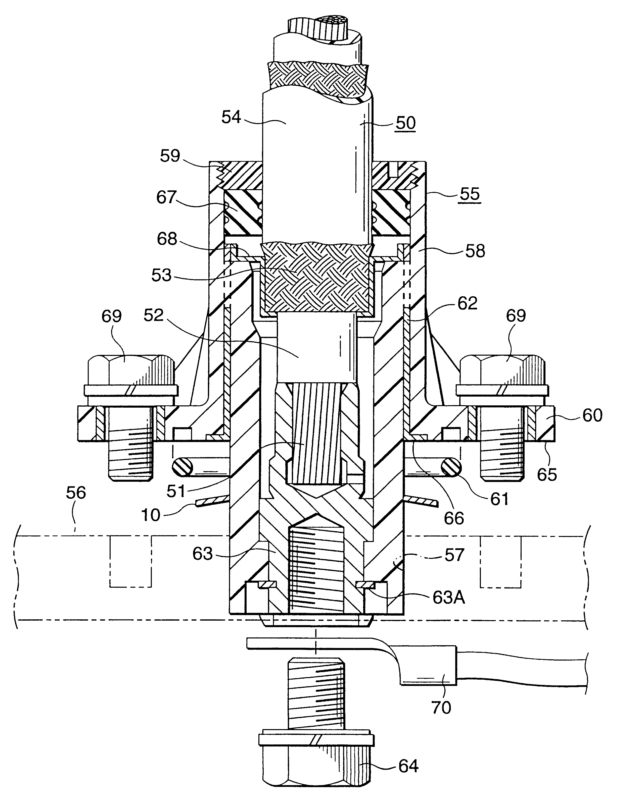
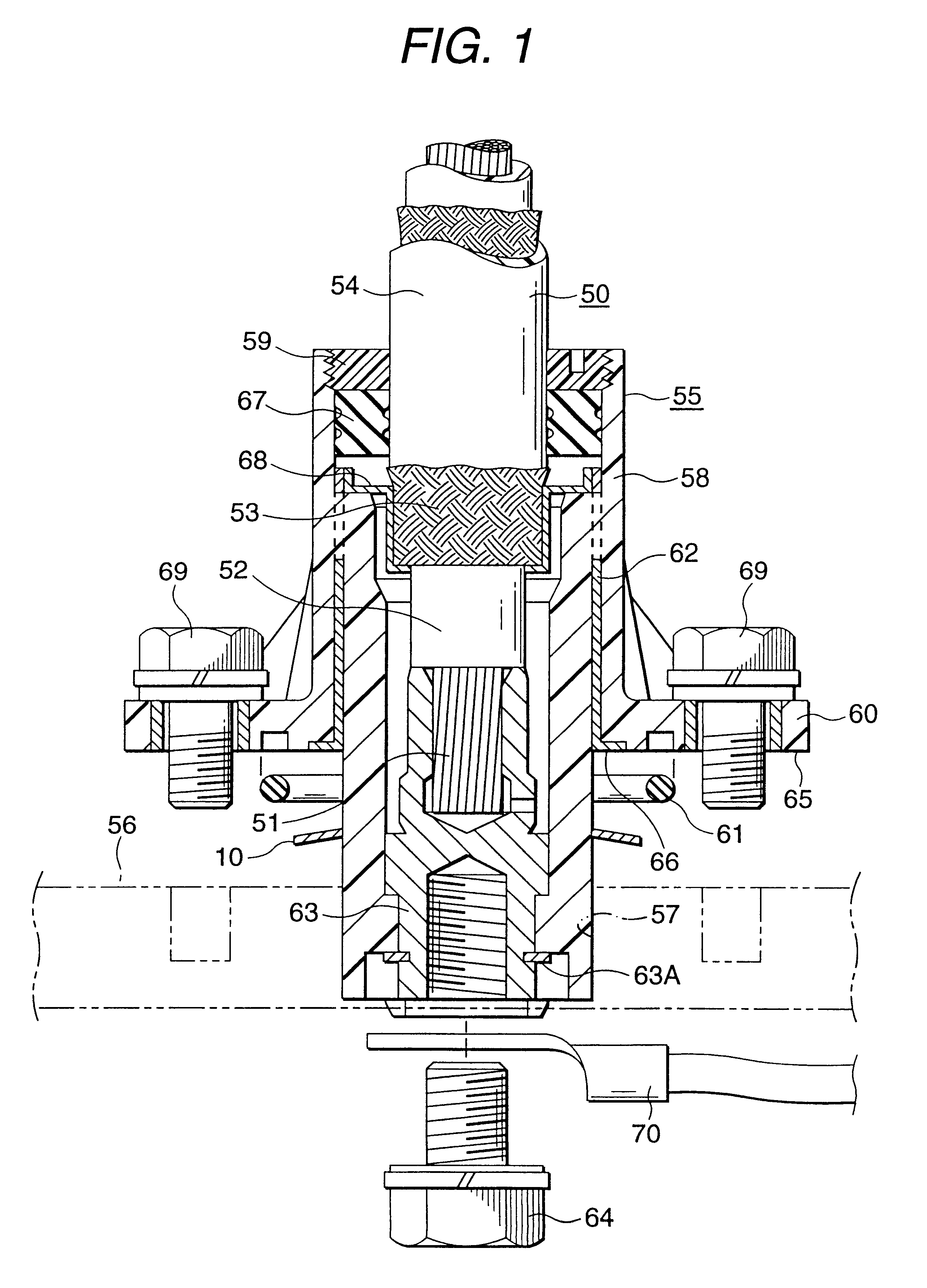
As shown in FIG. 1, the shield connector 55 includes, in the same manner as the related shield connector, the insulating cylinder 58, the rear holder 59, the flange 60 which can be fixed to the outer face of the motor case 56, the O-ring 61 adapted to be interposed between the motor case 56 and the flange 60, and the metal cylinder 62 which is coaxially inserted into the insulating cylinder 58.
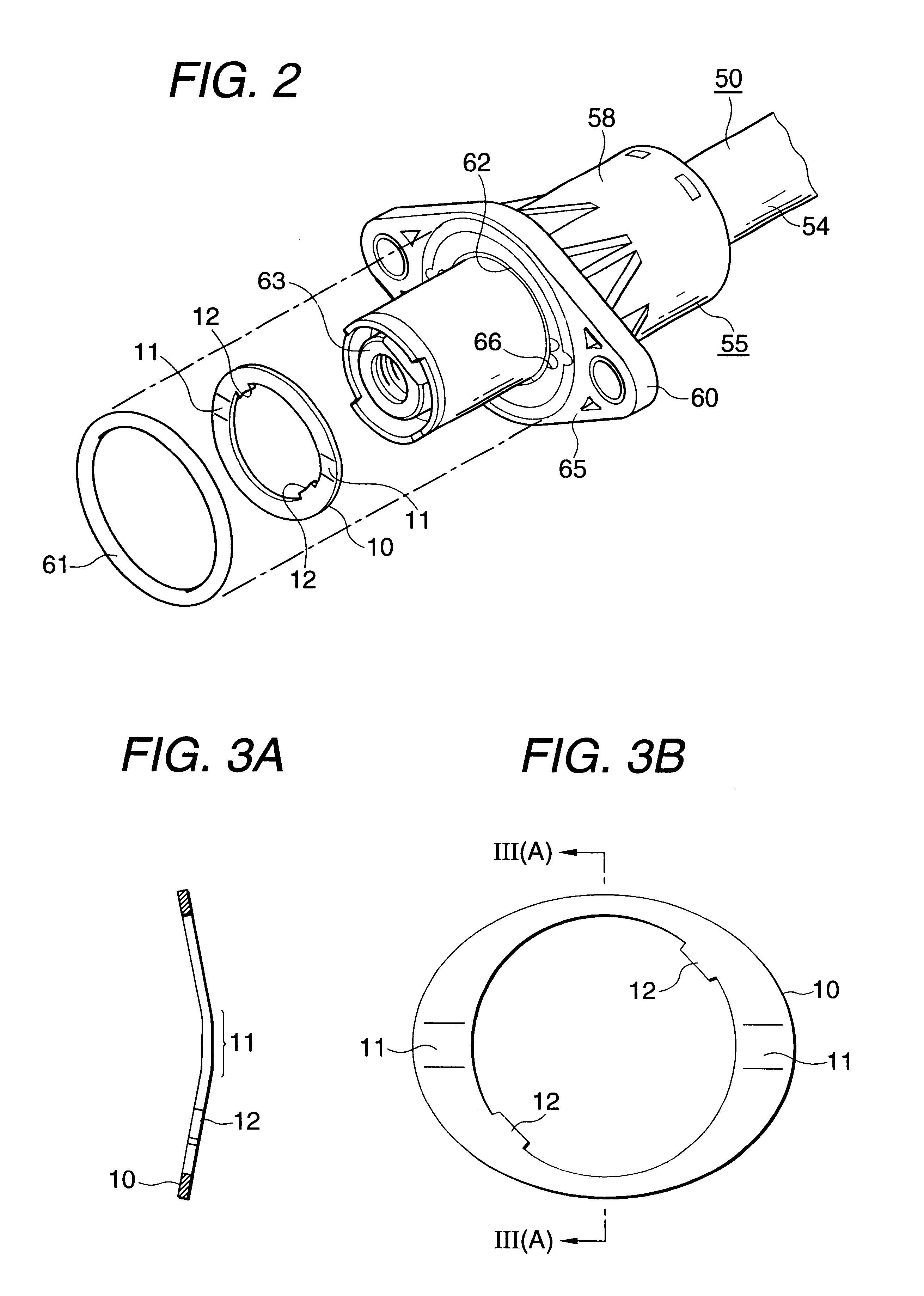
This shield connector 55 earths the braided shielding part 53 of the electric wire 50 and the motor case 56. When the shield connector 55 is connected to the motor case 56, a resilient conductive contact body 10 is interposed between the motor case 56 and the...
PUM
 Abstract
Description
Claims
Application Information