

CNC machine center with double-speed shifting feature in X and Z axes
- Summary
- Abstract
- Description
- Claims
- Application Information
AI Technical Summary
Problems solved by technology
Method used
Image

Examples
Embodiment Construction
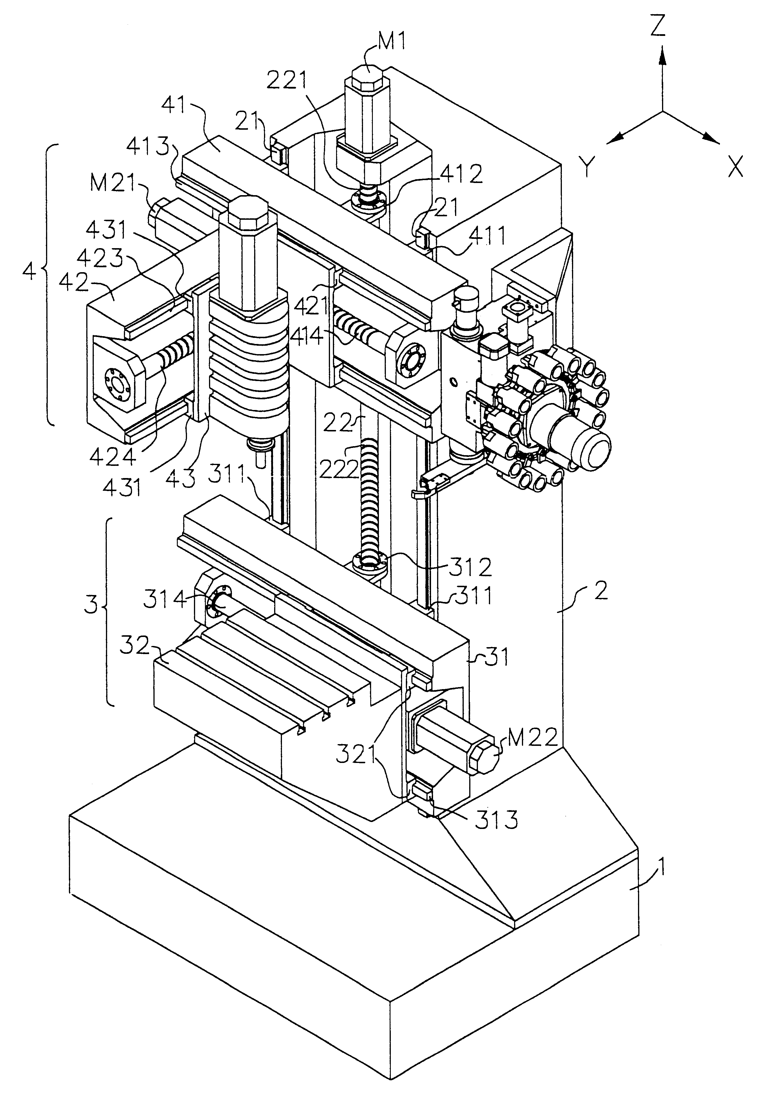
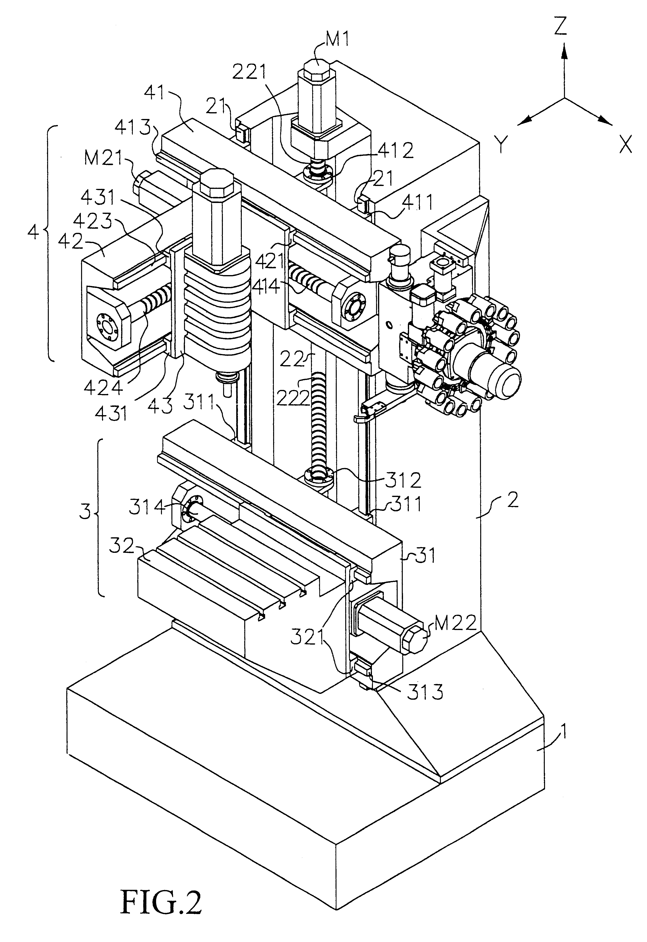
Certain terminology may be employed in the following description for convenience rather than for any limiting purpose. For example, the terms "forward," "rearward," "right," "left," "upper," and "lower" designate directions in the drawings to which reference is made, with the terms "inward," "inner," or "inboard" and "outward," "outer," or "outboard referring, respectively, to directions toward and away from the center for the referenced element, the terms "radial" and "axial" referring, respectively, to directions or planes perpendicular and parallel to the longitudinal central axis of the referenced element. Terminology of similar import other than the words specifically mentioned above likewise is to be considered being used for purposes of convenience rather than in any limiting sense. To facilitate illustration and description, X, Y and Z axes to be mentioned hereinafter are referred to three coordinate axes perpendicular to one another and indicated in the accompanying drawing...
PUM
 Abstract
Description
Claims
Application Information