

Internal combustion engine control apparatus and method
a control apparatus and internal combustion engine technology, applied in the direction of electric control, ignition automatic control, speed sensing governors, etc., can solve the problems of incomplete combustion state, limited feedback control based on ignition timing, and further deterioration of combustion sta
- Summary
- Abstract
- Description
- Claims
- Application Information
AI Technical Summary
Benefits of technology
Problems solved by technology
Method used
Image

Examples
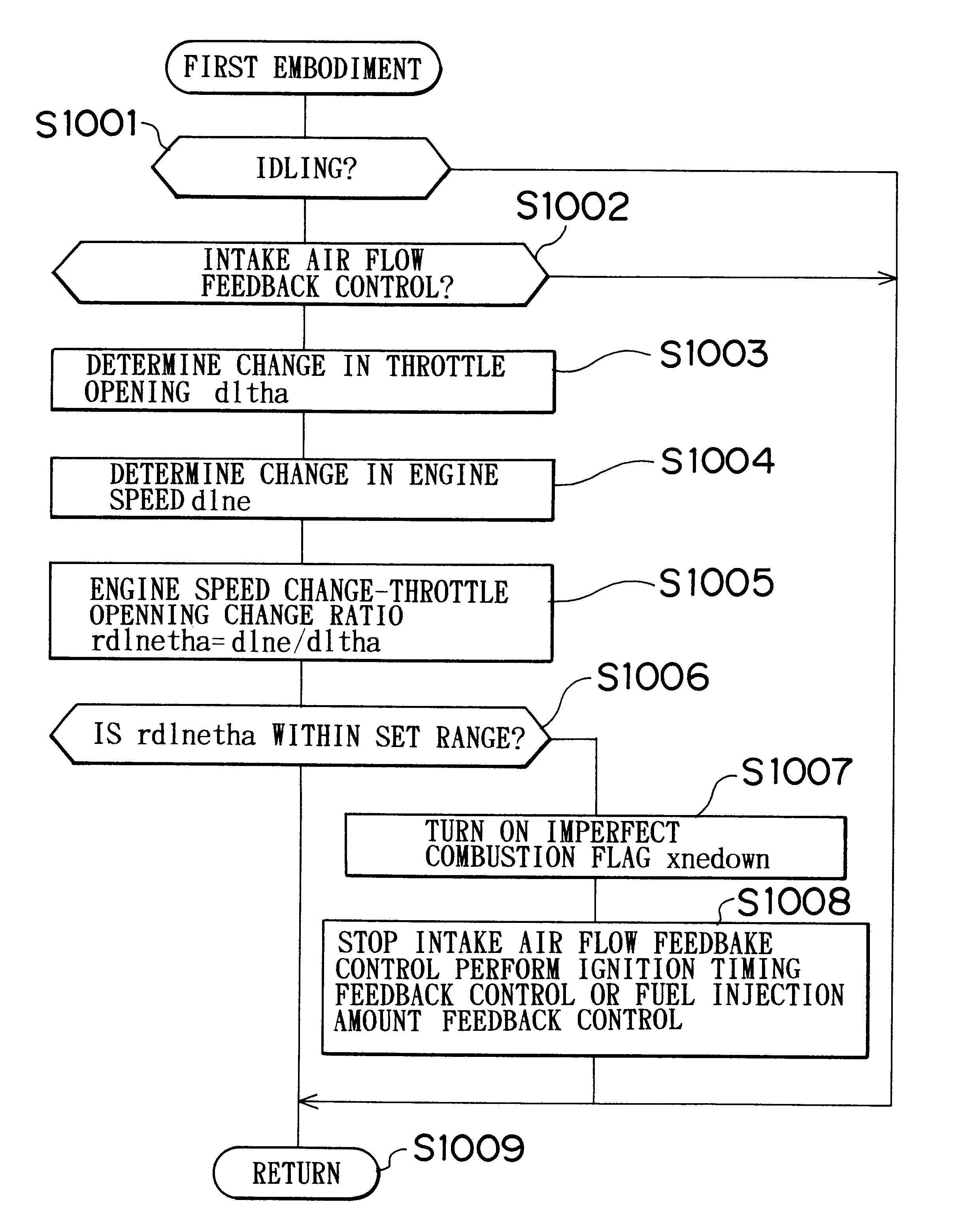
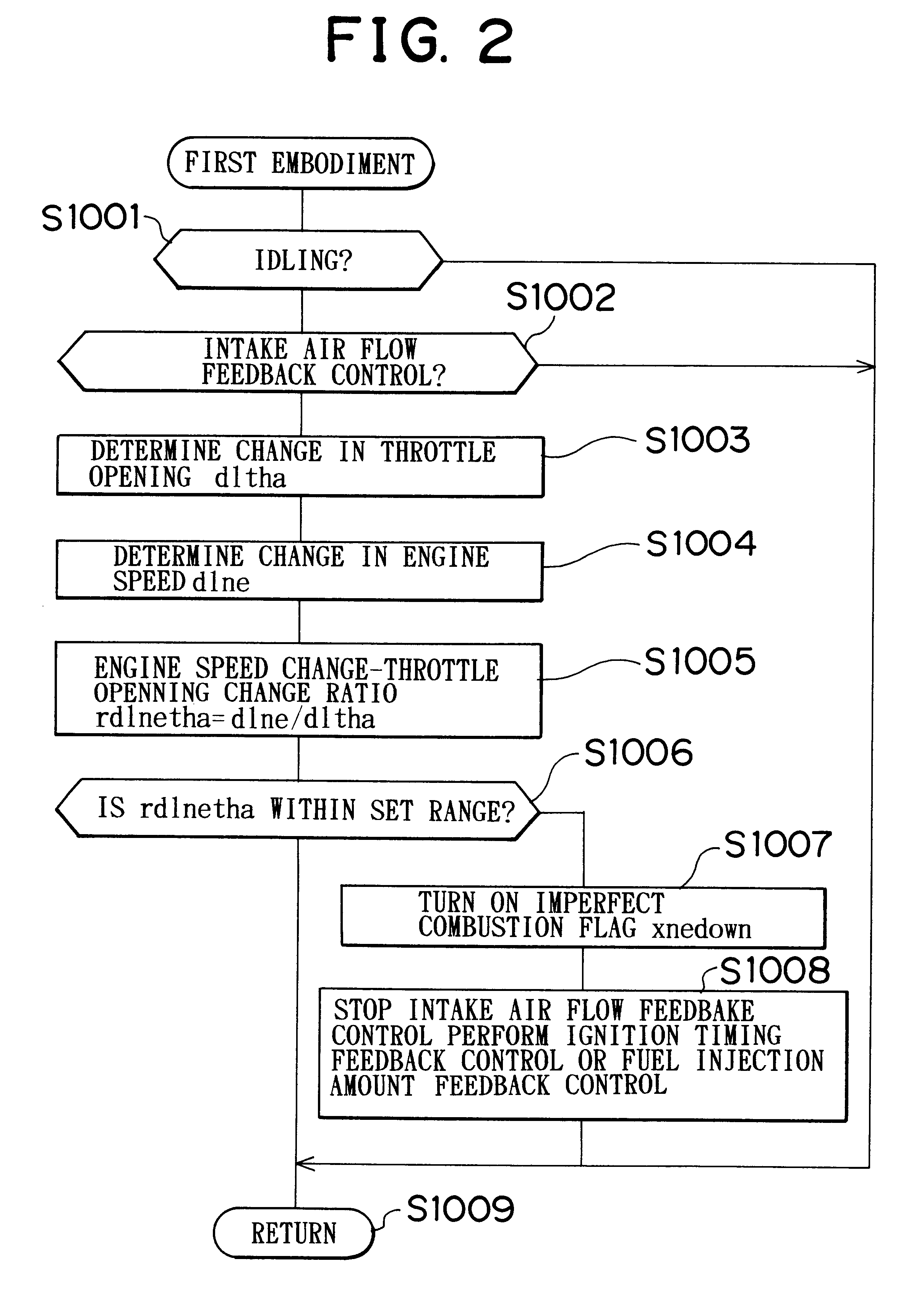
first embodiment
MODIFICATION OF FIRST EMBODIMENT
In the modification of the first embodiment, if the imperfect combustion state occurs during the intake air flow feedback control, the control is switched to the ignition timing feedback control or the fuel injection amount feedback control, as in the first embodiment. In the modification, however, whether the imperfect combustion state has occurred is determined based on the deviation of the engine rotation speed from a target value.
FIG. 3 is a flowchart illustrating a control operation according to the modification of the first embodiment. Steps 1101, 1102 in FIG. 3 are the same as steps 1001, 1002 in the first embodiment in FIG. 2, and therefore will not be described again. If the determination is negative in either one of steps 1101, 1102, the process jumps to step 1110 to return, without any further processing being executed. If the determination is affirmative in both steps 1101, 1102, the process proceeds to step 1103.
In step 1103, the ECU 10 d...
second embodiment
MODIFICATION OF SECOND EMBODIMENT
In the modification of the second embodiment, if the imperfect combustion state occurs during the ignition timing feedback control, the control is switched to the fuel injection amount feedback control, as in the second embodiment. In the modification, however, whether the imperfect combustion state has occurred is determined based on the deviation of the engine rotation speed from a target value.
Similar to the second embodiment, the modification of the second embodiment is performed when the intake air flow feedback control is inappropriate and has been switched to the ignition timing in the first embodiment.
FIG. 5 is a flowchart illustrating a control operation according to the modification of the second embodiment. The flowchart of FIG. 5 is basically the same as the flowchart of the modification of the first embodiment.
Steps 2101, 2102 in FIG. 5 are the same as steps 2001, 2002 in the second embodiment, and therefore will not be described again. ...
third embodiment
MODIFICATION OF THIRD EMBODIMENT
In the modification of the third embodiment, if the imperfect combustion state occurs during the fuel injection amount feedback control, the control is switched to the ignition timing feedback control, as in the third embodiment. In the modification, however, whether the imperfect combustion state has occurred is determined based on the deviation of the engine rotation speed from a target value.
Similar to the third embodiment, the modification of the third embodiment is performed when the intake air flow feedback control is inappropriate and has been switched to the fuel injection amount in the first embodiment.
FIG. 7 is a flowchart illustrating a control operation according to the modification of the third embodiment. The flowchart of FIG. 7 is basically the same as the flowchart of the modification of the first embodiment.
Steps 3101, 3102 in FIG. 7 are the same as steps 3001, 3002 in the third embodiment, and therefore will not be described again. I...
PUM
 Abstract
Description
Claims
Application Information