
Spherical body transport apparatus

a technology of spherical bodies and transport apparatuses, which is applied in the direction of transportation and packaging, grinding feeders, manufacturing tools, etc., can solve the problems of spherical body transport apparatus, which has not been realized so far

Inactive Publication Date: 2002-04-09
DISCO CORP
View PDF6 Cites 20 Cited by
  • Summary
  • Abstract
  • Description
  • Claims
  • Application Information

AI Technical Summary

Problems solved by technology

However, a spherical body transport apparatus, which can be used preferably in the transport of a small spherical body such as a spherical semiconductor, has not been realized so far.
Advantageously, the vent has a cross sectional shape and dimensions which do not allow the spherical body to pass therethrough.

Method used


Image

  • Spherical body transport apparatus
  • Spherical body transport apparatus
  • Spherical body transport apparatus

Examples


Embodiment Construction

Preferred embodiments of a spherical body transport apparatus constituted in accordance with the present invention will now be described in further detail with reference to the accompanying drawings.

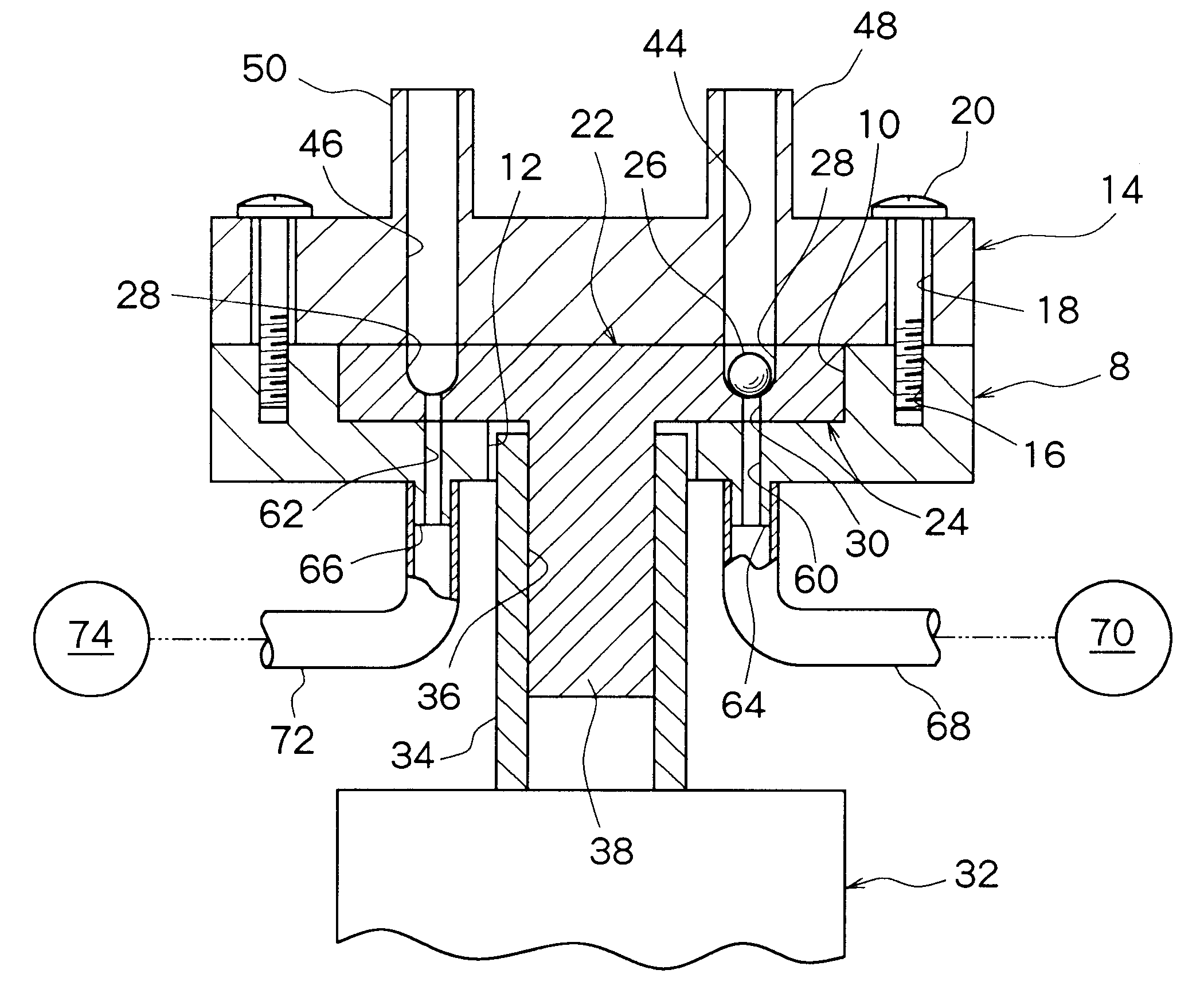
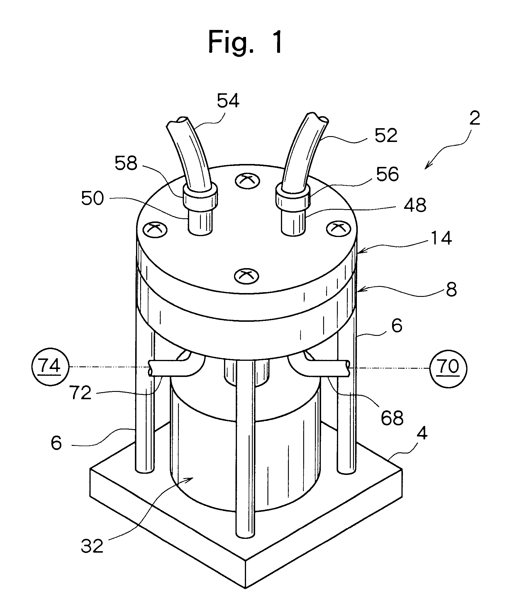
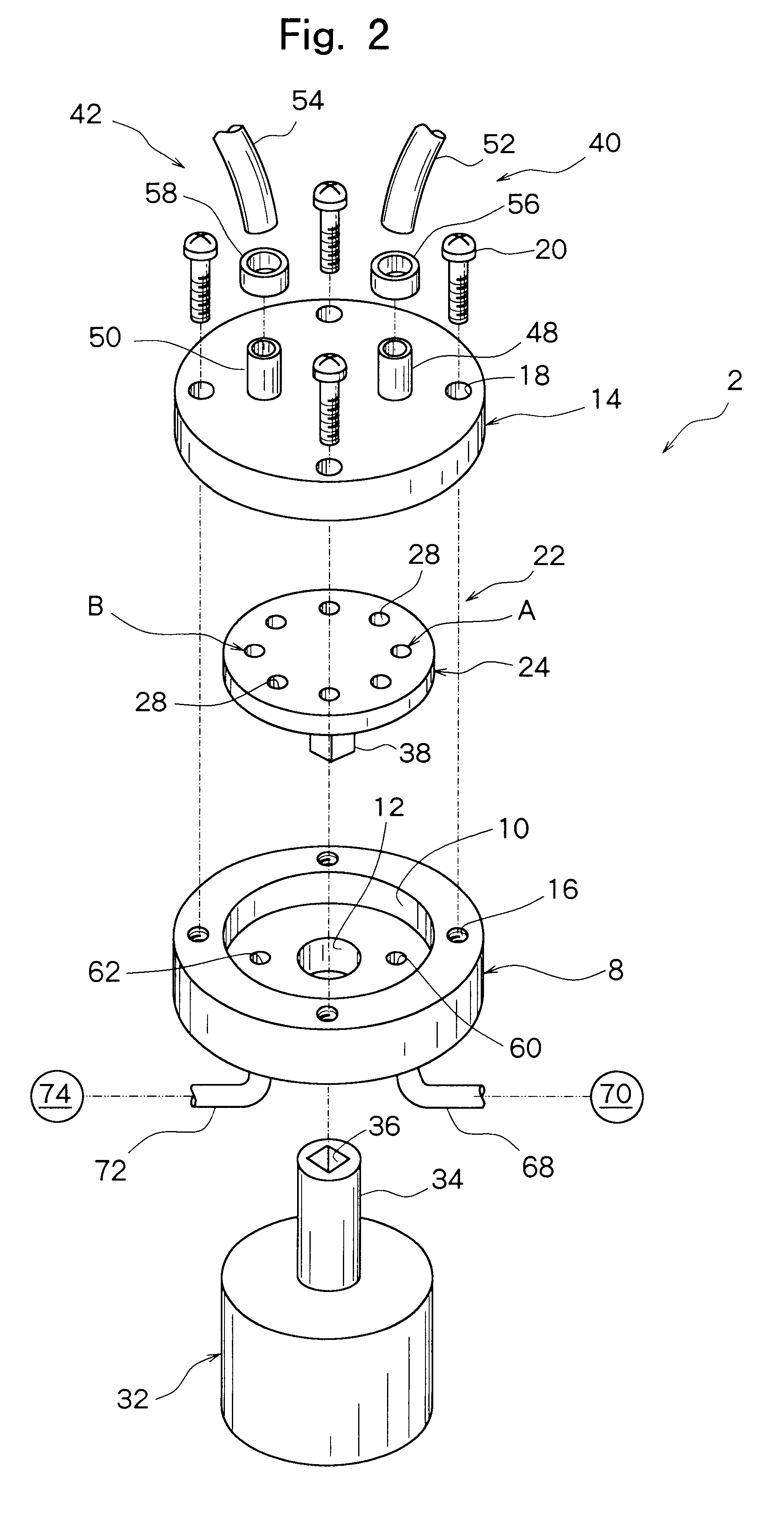
FIGS. 1, 2 and 3 show a preferred embodiment of a spherical body transport apparatus constituted in accordance with the invention. The illustrated spherical body transport apparatus designated entirely as the numeral 2 has a stationary board 4 which may be shaped like a square plate, as shown in FIG. 1. On the stationary board 4, four support pillars 6 (three of them are shown in FIG. 1) extending substantially vertically upwardly are fixed by a suitable method, such as bonding. To an upper end of each of the four support pillars 6, a lower stationary disk 8 is fixed by a suitable method, such as bonding. As will be understood clearly from FIGS. 2 and 3, a circular depression 10 is formed in the center of an upper surface of the lower stationary disk 8 disposed substantially horizontally...


PUM


Abstract

A spherical body transport apparatus applicable in accepting a small spherical body, such as a spherical semiconductor, from a first spherical body treating device and feeding it to a second spherical body treating device. Such a spherical body transport apparatus includes a spherical body holding component having at least one spherical body accommodating component and designed to hold a spherical body temporarily, a spherical body carry-in component for carrying the spherical body into the spherical body accommodating component of the spherical body holding component, and a spherical body carry-out component for carrying the spherical body out of the spherical body accommodating component of the spherical body holding component.

Description

This invention relates to a spherical body transport apparatus suitable for transporting a small spherical body such as a spherical semiconductor. More specifically, the invention relates to a spherical body transport apparatus which can be applied in accepting a small spherical body from a first spherical body treating device and feeding it to a second spherical body treating device.DESCRIPTION OF THE PRIOR ARTRecently, it has been proposed to form an integrated circuit on the surface of a spherical semiconductor such as spherical silicon, called ball semiconductor. Such a spherical semiconductor is a small spherical body with a diameter of, for example, about 1 mm. Prior to forming the integrated circuit on the surface of the spherical semiconductor, it is necessary to polish the surface of the spherical semiconductor thoroughly. Japanese Patent Application No. 11-119490 (Title of the Invention: Ball Polishing Device, Filing date: Apr. 27, 1999), assigned to the assignee of the pr...

Claims


Application Information

Patent Timeline
IPC IPC(8): B24B11/00B24B41/00B23P19/00B23Q7/00
CPCB23P19/001B24B41/005B24B11/00B23P19/005
Inventor TAKAZAWA, TORU
Owner DISCO CORP
Learn More