

Spread spectrum communication system
a technology of communication system and spread spectrum, which is applied in the direction of radio transmission, electrical equipment, transmission, etc., can solve the problems of consuming a lot of electrical power, wasting a lot of time when the spread code is long, and reducing search tim
- Summary
- Abstract
- Description
- Claims
- Application Information
AI Technical Summary
Problems solved by technology
Method used
Image

Examples
first embodiment
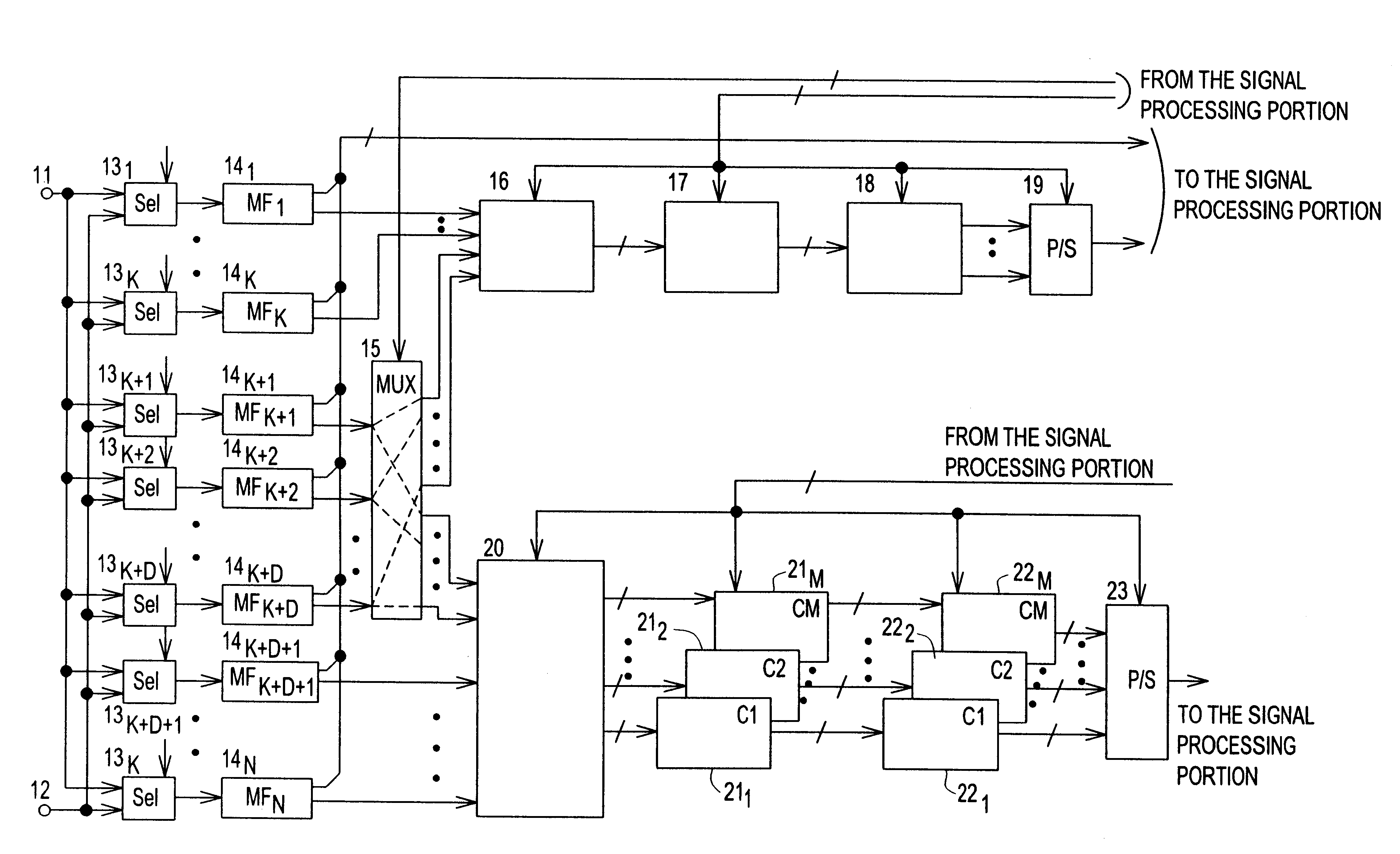
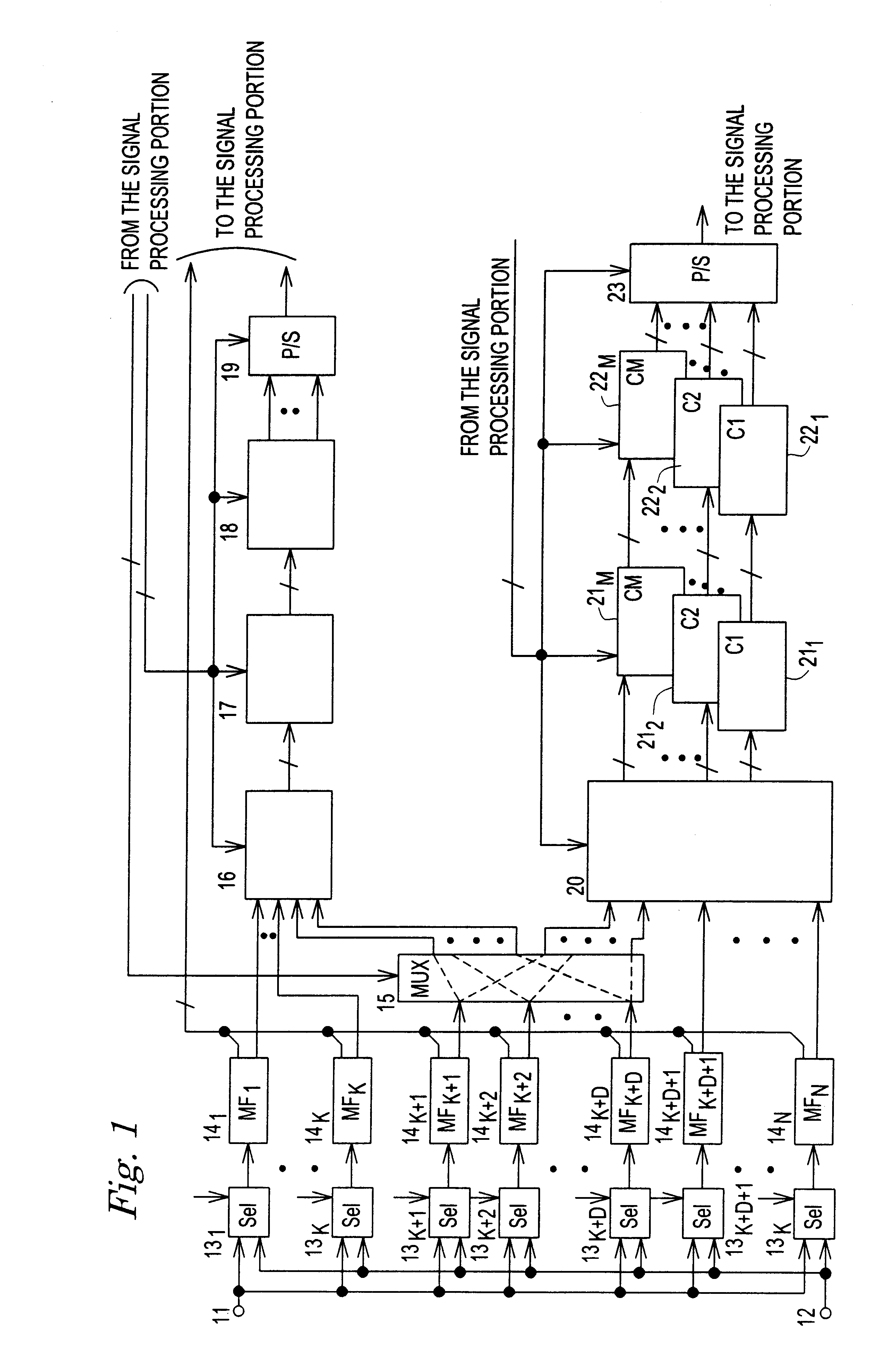
FIG. 1 is a block diagram of a receiver for a D-CDMA cellular system. The reference 11 designates a signal input terminal for receiving the first branch base band signal generated by a quadrature detection from a spread spectrum signal received by a receiver antenna for the first branch (not shown), the reference 12 designates an input signal terminal for receiving the second branch base band signal generated by a quadrature detection from the spread spectrum signal received by a receiver antenna for the second branch (not shown). An in-phase component (I-component) and a quadrature component (Q-component) of the base band signals of first and second branches are input from the input terminals 11 and 12, respectively.
The base band signals are selected by a plurality of selectors 131 to 13N parallelly connected to the terminals 11 and 12 for alternatively selecting the first or second branch. The selected signal is input to matched filters 141 to 14N corresponding to the selectors 13...
second embodiment
FIGS. 6 to 18 show a second embodiment for the receiver. In FIG. 6, a matched filter for the diversity reception of two antenna branches includes two sampling and holding circuit groups SHG1 and SHG2 corresponding to signals Vb1 and Vb2 of the branches. SHGL and SHG2 include a plurality of sampling and holding circuits SH11 to SH1n and SH21 to SH2n, respectively. SHG1 and SHG2 are commonly connected to a plurality of matched filters MUL1 to MULm, which selectively read data of one of the groups. Since the matched filters are commonly used for the data of SHG1 and SHG2, the circuit size is remarkably decreased.
The sampling and holding circuits of each group successively take data without transferring data between the sampling and holding circuits. The transfer error is prevented.
A plurality of selectors SEL11 to SEL1n are provided in the matched filter MUL1 corresponding to the sampling and holding circuits in SHG1 and SHG2. For example, SEL11 receives the outputs from SH11 and SH21....
third embodiment
FIG. 19 shows a matched filter bank of the The reference designates an analog signal input terminal for receiving a base band signal obtained from a signal received from an antenna. The reference 12 designates a group of sampling and holding circuits SH1 to SH256 which are parallelly connected to the terminal 11. The sampling and holding circuits are controlled by a control signal shown by "0" and "1" at the upper adjacent area of the sampling and holding circuits in FIG. 19. When the control signal is "1", the sampling and holding circuit takes new data. The control signal is shifted in response to a sampling clock CL.
The initial condition of the control signal for SH1 is "1" and SH1 takes the analog signal from the terminal 11. In the next timing, the control signal for SH2 is "1" and for others are "0", so SH2 takes the signal. Then, SH3, SH4, . . . take the signal successively. After the sampling by SH256, the sampling cycle from SH1 is restarted.
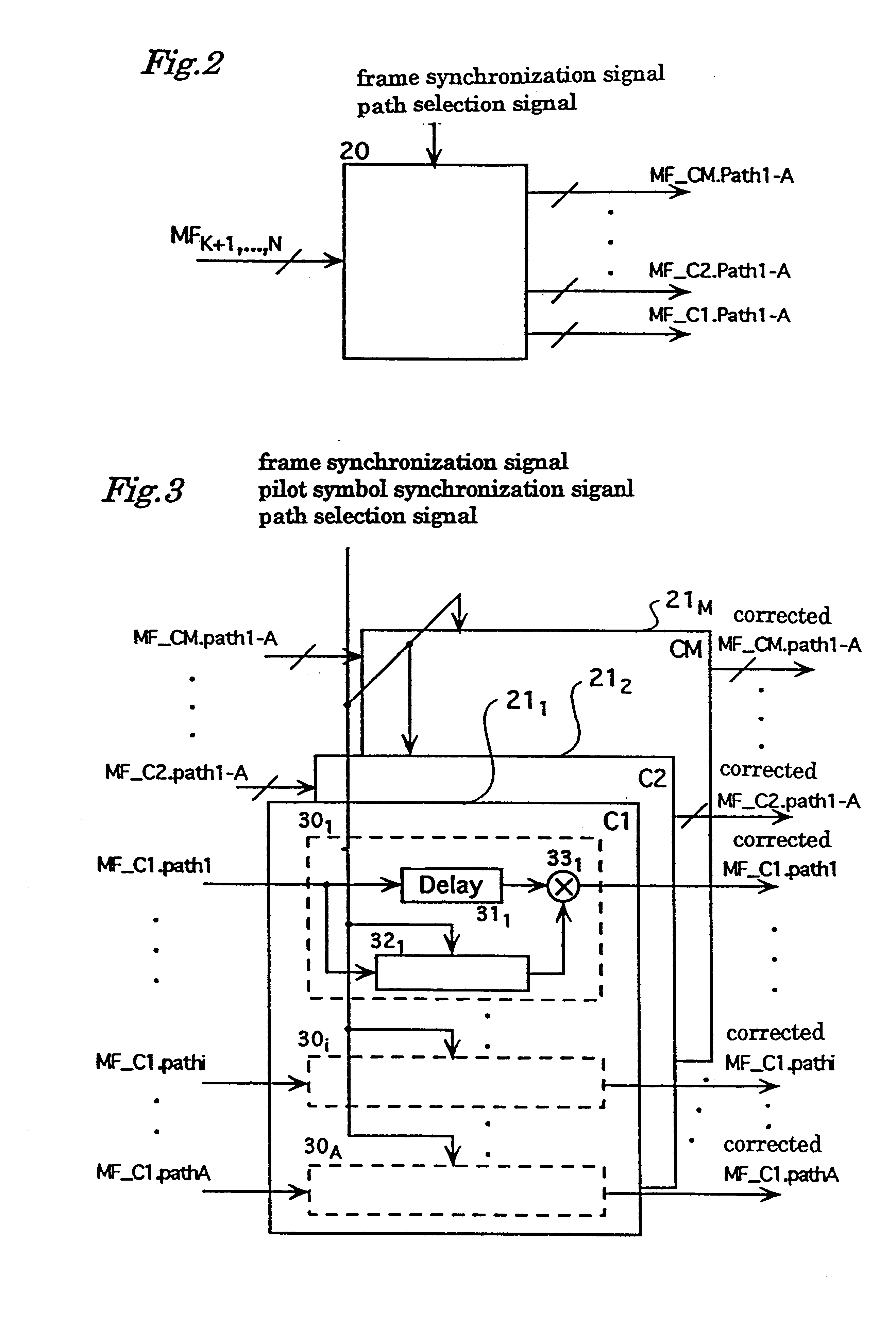
The reference 13 designates a P...
PUM
 Abstract
Description
Claims
Application Information