
Injector with a multilayer piezoelectric actuator

a piezoelectric actuator and injector technology, applied in the direction of valve operating means/releasing devices, machines/engines, liquid fuel feeders, etc., can solve the problem of increasing the diameter of the injector in the region

Inactive Publication Date: 2002-04-16
ROBERT BOSCH GMBH
View PDF7 Cites 13 Cited by
  • Summary
  • Abstract
  • Description
  • Claims
  • Application Information

AI Technical Summary

Benefits of technology

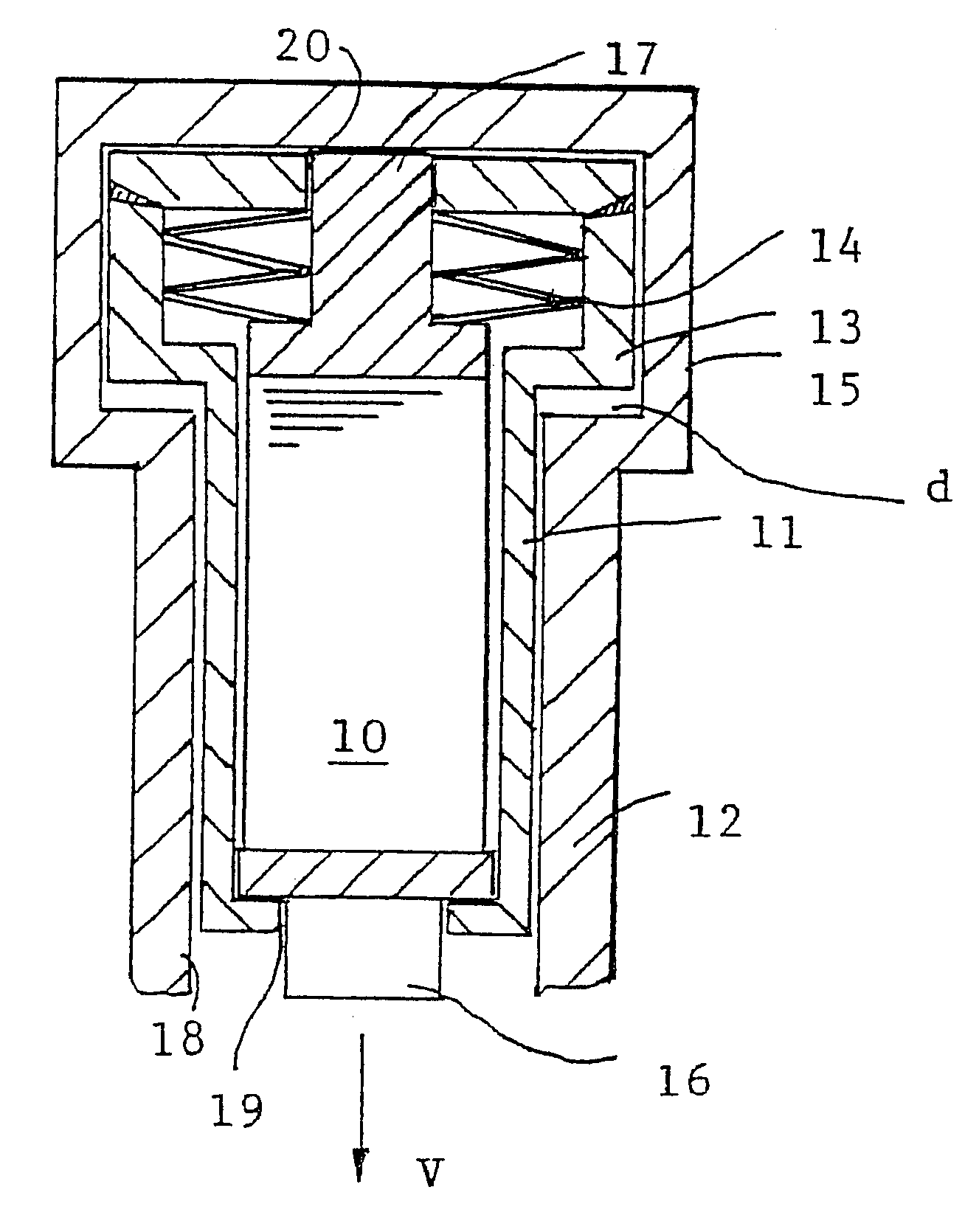
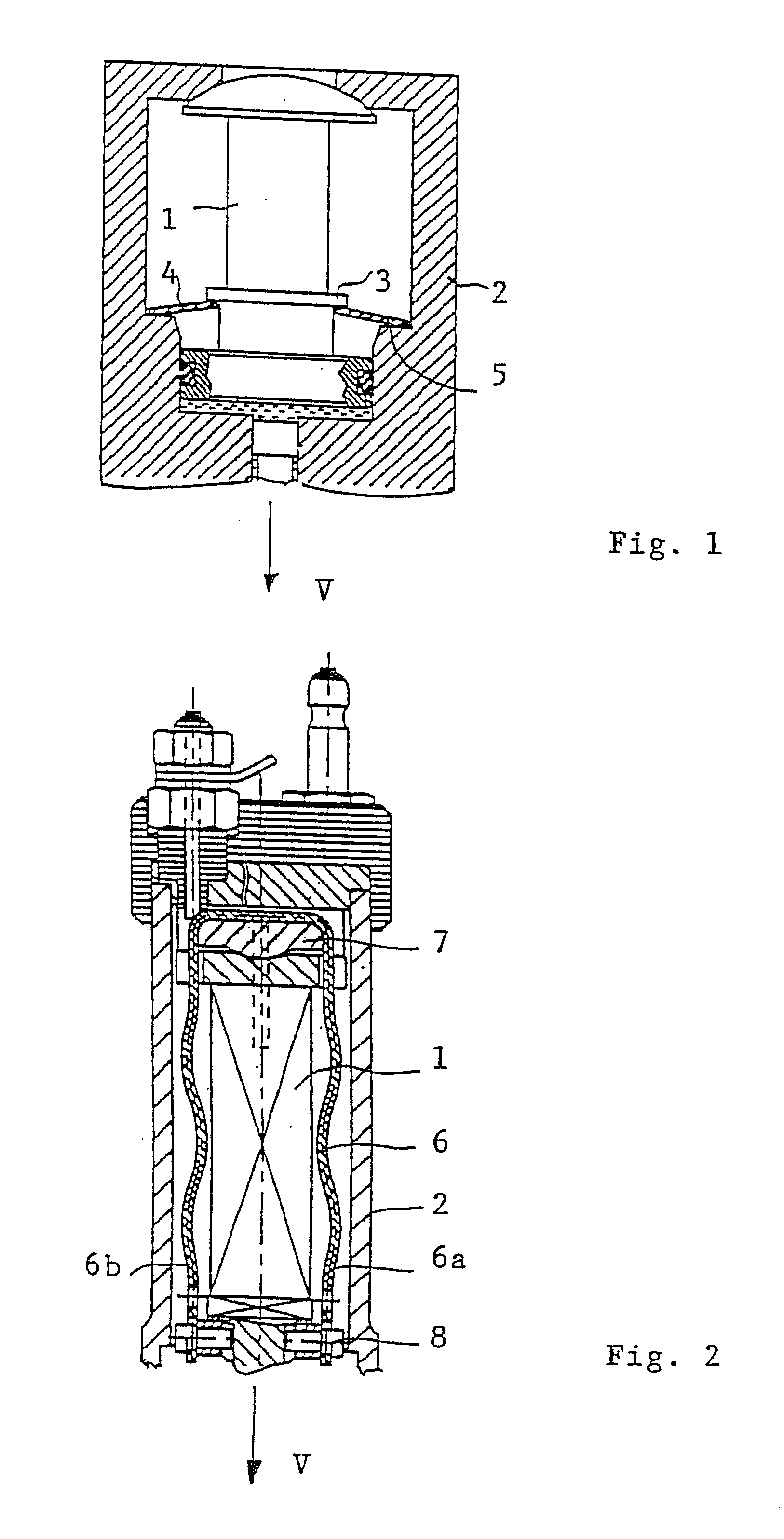
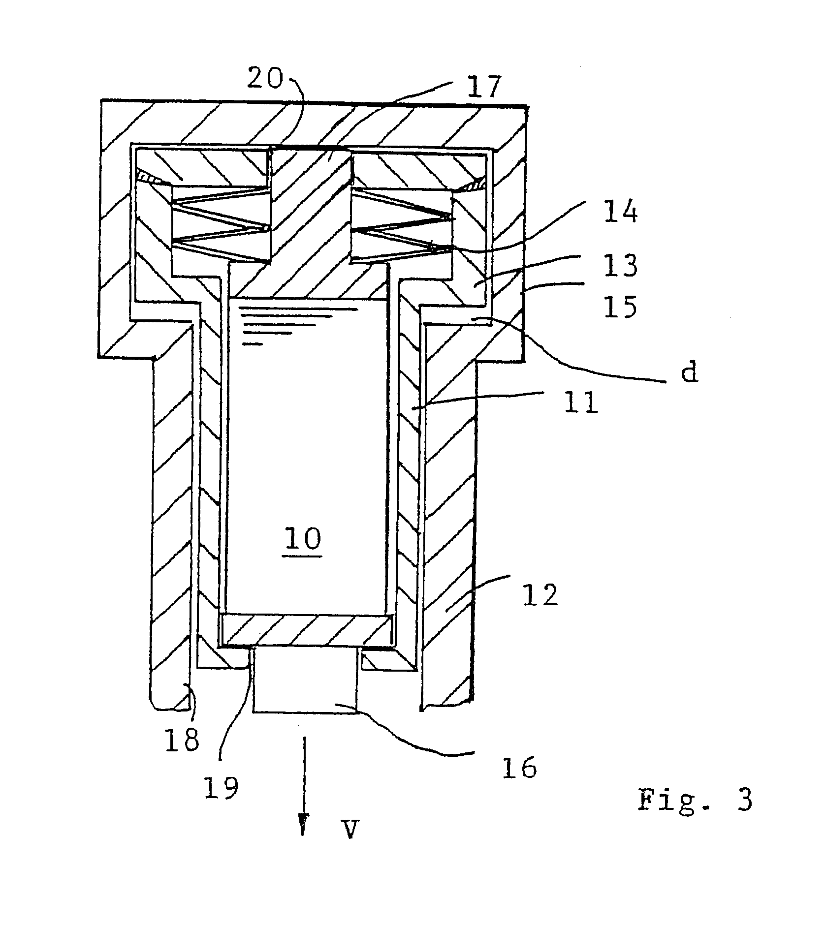
It is thus an object of the invention to make an injector with a multilayer piezoelectric actuator that is better suited to common rail Diesel injection systems of motor vehicles and in which the outer diameter of the injector housing can be as small as possible.An essential aspect of an injector according to the invention with a multilayer piezoelectric actuator is that the prestressing means have at least one cup spring, which in prestressing fashion engages the face end of the actuator body opposite an injector valve, as well as a force transmission member seated in the injector housing and axially movable therein, which member transmits the spring force of the cup spring or springs to the face and, toward the valve, of the actuator body.Preferably, the actuator body has a circular- cylindrical cross-sectional form. In this case, at least in the region of the actuator body, the sleevelike injector housing has a circular-cylindrical inner and outer contour and surrounds the actuator body and the force transmission member, which forms a circular-cylindrical clamping sleeve, and the actuator body abuts a radial inner wall, toward the valve, of the clamping sleeve, and the cup spring or springs engage between the opposed inner wall on the face end of the clamping sleeve and the adjacent face end of the actuator body.Thus the cup spring or strings that effect the prestressing are provided behind the actuator body, that is, on the side of the actuator body remote from the valve, thus making a slender design of the injector in the region of the actuator body possible. In other words, the thicker actuator head having the cup spring or cup springs is located in the noncritical region of the cylinder head of the internal combustion engine.With this arrangement, relatively short common rail injectors with a multilayer piezoelectric actuator that are no longer than the conventional magnet valve injectors can be produced.The above and further advantageous characteristics of the injector of the invention will become even clearer in the ensuing description of a preferred exemplary embodiment when this description is read in conjunction with the accompanying drawings.FIG. 1, in the form of a schematic longitudinal section, shows the already-described known injector, with a prestressing element, on the side toward the valve, embodied as a cup spring.FIG. 2, in the form of a schematic longitudinal section, shows the other already-described known injector, which as its prestressing element contains a two-legged prestressing bracket.FIG. 3, in the form of a schematic longitudinal section, shows a preferred exemplary embodiment of an injector according to the invention with a multilayer piezoelectric actuator.

Problems solved by technology

The result is that the prestressing elements used in conventional common rail Diesel injection systems of the prior art undesirably increase the diameter of the injector in the region of the piezoelectric actuator.

Method used


Image

  • Injector with a multilayer piezoelectric actuator
  • Injector with a multilayer piezoelectric actuator
  • Injector with a multilayer piezoelectric actuator

Examples


Embodiment Construction

Exemplary Embodiment

In FIG. 3, a cylindrical actuator body 10 of a multilayer piezoelectric actuator, which can take the form of a multilayer laminate of stacked layers of piezoelectric material and intervening metal or electrically conducting layers serving as electrodes, is prestressed on a face end by prestressing means. The prestressing means comprise a cup spring packet 14 and a cylindrical clamping sleeve 11, which are seated inside a cylindrical injector housing 12. The actuator body 10 of the multilayer piezoelectric actuator ends at the face end pointing toward the valve V, in a pressure bolt 16 which at that point passes through a central bore 19 in the cylindrical clamping sleeve 11. The face end of the actuator body 10 opposite the end toward the valve ends in a bracing element 17, which in turn has a boltlike end that protrudes through the central bore 20 of the clamping sleeve 11 and there abuts a radial inner wall of the injector housing 12.

If a pulsating electrical v...


PUM


Abstract

An injector for common rail Diesel injection systems of motor vehicles, having a multilayer piezoelectric actuator which has a multilayer actuator body. The actuator body is prestressed on a face end by a prestressing device and is seated inside a center longitudinal bore of an injector housing. The injector is characterized in that the prestressing device have at least one cup spring, which in a prestressing movement engages the face end of the actuator body opposite an injector valve (V), as well as a force transmission member seated in the injector housing and axially movable therein, the transmission member transmits the spring force of the at least one cup spring to the face end, toward the valve, of the actuator body.

Description

PRIOR ARTThe invention relates to n injector, in particular for common rail Diesel injection s stems of motor vehicles, having a multilayer piezoelectric actuator which has a multilayer actuator body, prestressed on a face end by a prestressing means and seated inside a longitudinal bore of an injector housing.From International Patent Disclosure WO 94 / 19598 (Siemens AG), an injector of this kind with a multilayer piezoelectric actuator is known. The accompanying FIG. 1 shows the portion of the known injector located round the actuator body. In the known injector, the means that prestress the actuator body 1 comprise a cup spring 4 toward the valve, which on one end rests on or engages an annular flange 3 located on the face end toward the valve of the actuator body 1 and on the other end rests or engages a radially inward- protruding shoulder 5 of the injector housing 2. In this case, the injector housing 2 itself forms the means for transmitting the prestressing force, exerted by ...

Claims


Application Information

Patent Timeline
Patent Type & Authority Patents(United States)
IPC IPC(8): F02M51/06F02M47/02F02M63/00H01L41/083H01L41/09
CPCF02M51/0603F02M2200/21
Inventor BOECKING, FRIEDRICH
Owner ROBERT BOSCH GMBH
Learn More