Pull-to-release type latch mechanism for removable small form factor electronic modules

a technology of electronic modules and latches, which is applied in the direction of electrical apparatus, connection, coupling device connections, etc., can solve the problems of unprotected, latches latches themselves cannot be left in data ports, so as to achieve the effect of convenient replacemen

Inactive Publication Date: 2002-04-16
JDS UNIPHASE CORP
View PDF2 Cites 103 Cited by
  • Summary
  • Abstract
  • Description
  • Claims
  • Application Information

AI Technical Summary

Problems solved by technology

Therefore, the latch itself cannot be left in the data port, unprotected as such, and face the possibility of breakage from impacts or forces exerted thereon.
Such breakage is a problem presented by designs wherein the latch mechanism is not removed from the data port whenever a transceiver module is removed.
Remaining as part of the host device, a latch release member is obviously exposed to damage as it will project from the host device without a protective device to shield the latch device.

Method used


Image

  • Pull-to-release type latch mechanism for removable small form factor electronic modules
  • Pull-to-release type latch mechanism for removable small form factor electronic modules
  • Pull-to-release type latch mechanism for removable small form factor electronic modules

Examples


Embodiment Construction

AS CONTEMPLATED BY THE INVENTORS

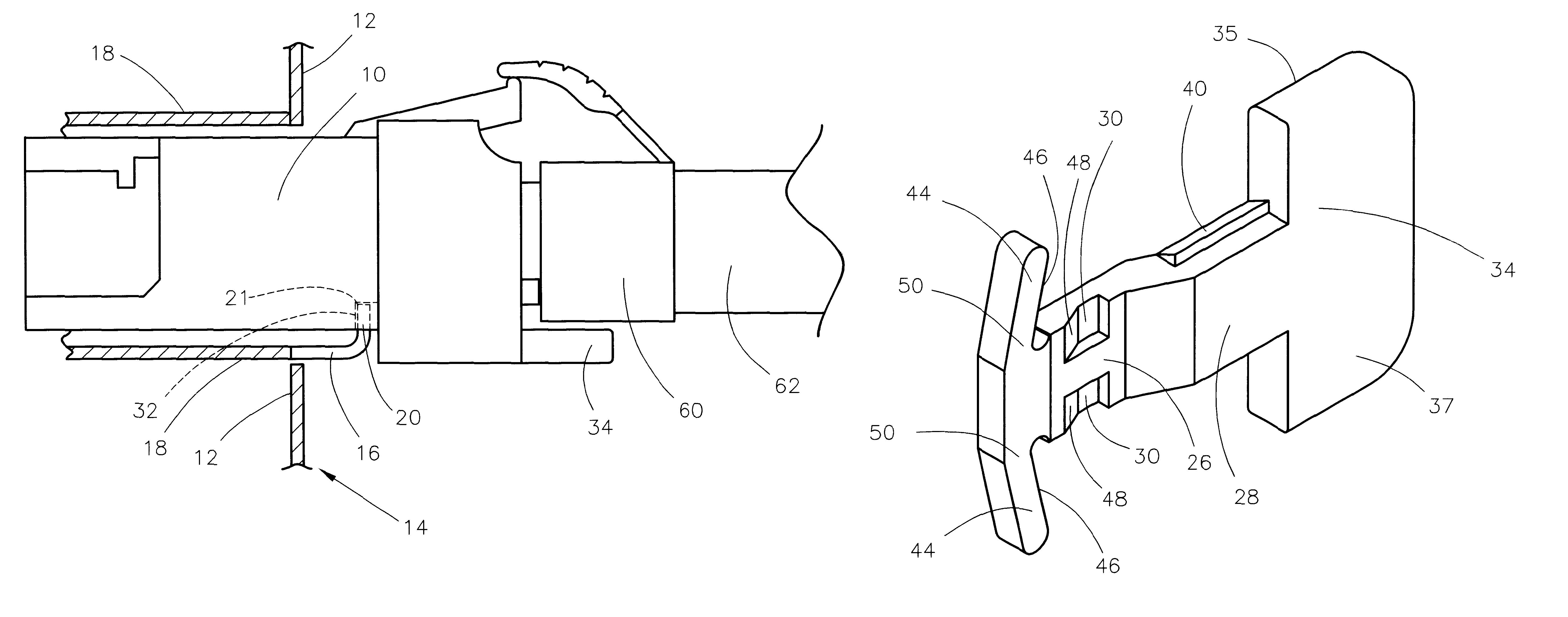
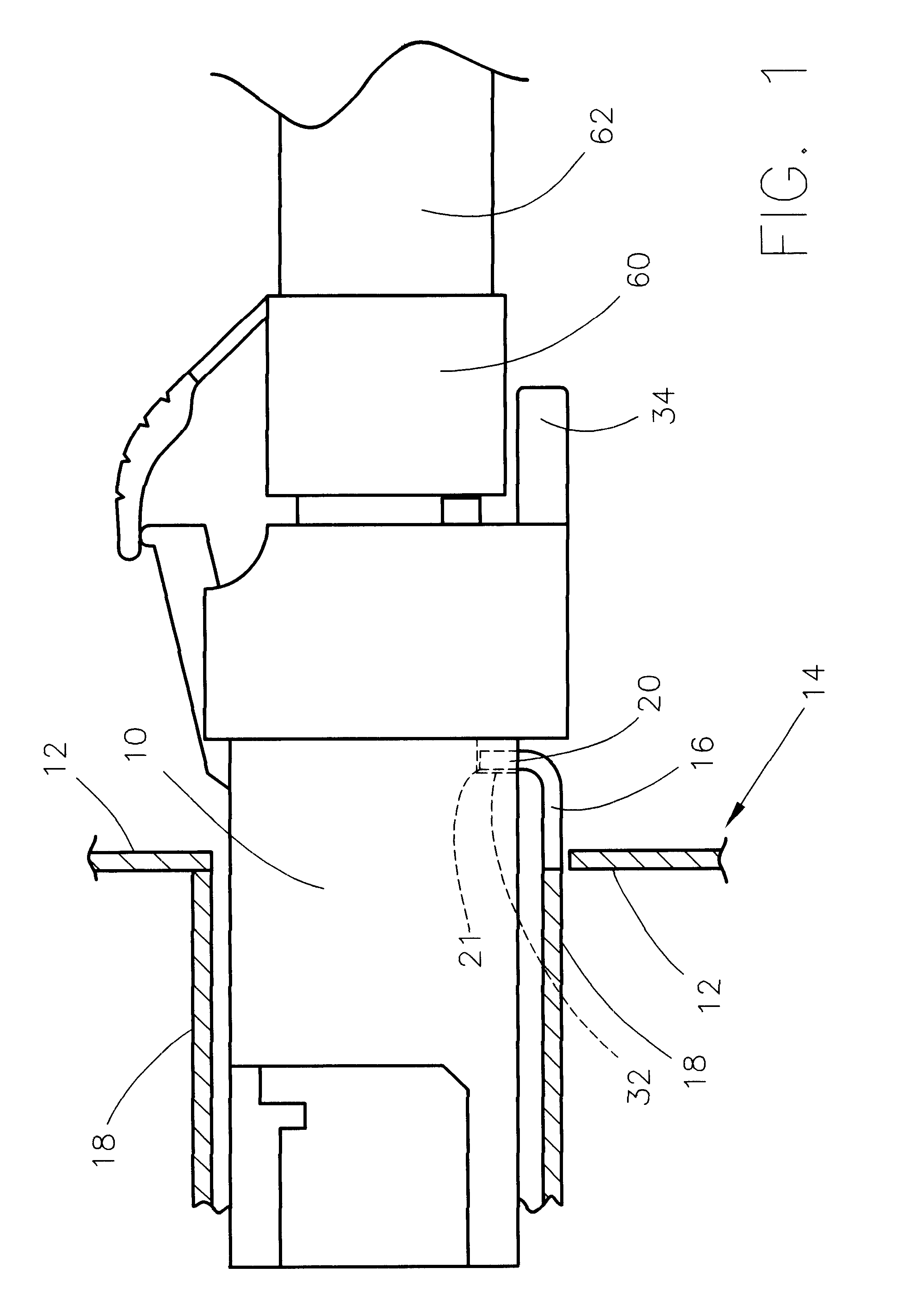
Referring to FIG. 1, the pull-to-release latch release member pull tab 34 is shown protruding from the transceiver module 10 and illustrates the transceiver module 10 latched into place by the latch member 16. The transceiver module 10 is shown inserted within the electro-magnetic interference shield or cage 18. A portion of the electro-magnetic interference cage 18 is formed both to be a cantilevered beam spring, functioning as latch member 16, and to deflect to permit passage of the transceiver module 10 upon insertion into the electro-magnetic interference cage 18.

Edge 21 of the upstanding portion or finger 20 of latch member 16 engages the transceiver module 10 to latch or retain the transceiver module 10 in the electro-magnetic interference cage 18 and is connected to the electronics (not shown) contained within the housing of the host device 14.

The transceiver module 10 is illustrated mated with a ferrule 60 on the end of a fiber optic cable 62....


PUM


Abstract

A latch mechanism using a natural unlatching, releasing, pull movement has a slidable latch release which is carried on a device being latched, such as an electronic module. This slidable latch release has a pair of recesses or cavities at least partially defining cams that engage and displace a latch member from engagement with a latching surface on the device being latched. A latch release member is provided with a pair of wing members that are resilient and are deformed as a result of movement of the latch release relative to the latched device. Deformation provides a bias to restore the latch release member to a position capable of permitting latching upon the reinsertion of the device into a host device, such as a computer or the like.

Description

CROSS REFERENCE TO RELATED UNITED STATES PATENT APPLICATIONSThe following are related co-pending United States patent applications:REMOVABLE SMALL FORM FACTOR FIBER OPTIC TRANSCEIVER MODULE CHASSIS, Ser. No. 09 / 489,870, filed Jan. 20, 2000, by Scott M. Branch, David P. Gaio and William K. Hogan;REMOVABLE LATCH AND BEZEL ELECTRO-MAGNETIC INTERFERENCE GROUNDING FEATURE FOR FIBER-OPTIC TRANSCEIVERS, Ser. No. 09 / 410,786, filed Oct. 1, 1999, by Scott M. Branch, David P. Gaio and William K. Hogan;REMOVABLE SMALL FORM FACTOR FIBER OPTIC TRANSCEIVER MODULE AND ELECTROMAGNETIC RADIATION SHIELD, Ser. No. 09 / 489,184, filed Jan. 20, 2000, by Scott M. Branch, David P. Gaio and William K. Hogan;PIVOTING TYPE LATCH FOR REMOVABLE ELECTRONIC DEVICES, Ser. No. 09 / 591,640, filed Jun. 9, 2000, by Scott M. Branch, Leland L. Day, David P. Gaio, Michael F. Hanley and William K. Hogan;PULL TYPE LATCH MECHANISM FOR REMOVABLE SMALL FORM FACTOR ELECTRONIC MODULES, Ser. No. 09 / 657,214, filed Sep. 7, 2000, by S...

Claims


Application Information

Patent Timeline
Patent Type & Authority Patents(United States)
IPC IPC(8): H01R13/627
CPCH01R13/6275
Inventor BRANCH, SCOTT M.GAIO, DAVID P.HANLEY, MICHAEL F.HOGAN, WILLIAM K.
Owner JDS UNIPHASE CORP
Why Eureka
Try Eureka