Method and structure of monolithically integrated pressure sensor using IC foundry-compatible processes

a pressure sensor and integrated technology, applied in the direction of fluid pressure measurement, fluid pressure measurement by electric/magnetic elements, instruments, etc., can solve the problems of bulk and surface machining techniques that have limitations, conventional pressure sensors have limitations in size, performance and cost, and mems based devices still have limitations, etc., to achieve the lowest cost, the effect of smallest form factor and high performan

Active Publication Date: 2010-07-08
MOVELLA INC
View PDF5 Cites 82 Cited by
  • Summary
  • Abstract
  • Description
  • Claims
  • Application Information

AI Technical Summary

Benefits of technology

[0009]The present invention relates to integrating a MEMS pressure sensor on top of a CMOS substrate monolithically using IC-Foundry compatible processes. In some embodiments, the CMOS substrate is completed first using standard IC processes. A diaphragm is then added on top of the CMOS. In one embodiment, the diaphragm is made of deposited thin films with stress relief corrugated structure. In another embodiment, the diaphragm is made of a single crystal silicon material that is layer transferred to the CMOS substrate. In a specific embodiment, the integrated pressure sensor is encapsulated by a thick insulating layer at the wafer level. The monolithically integrated pressure sensor that adopts IC foundry-compatible processes yields the highest performance, smallest form factor, and lowest cost. The monolithically integrated pressure sensor can be used in a variety of applications, for example, for integrating a microphone device with signal processing and logic circuits.

Problems solved by technology

Although highly successful and widely used, conventional pressure sensors have limitations in size, performance, and costs.
Such bulk and surface machining techniques have limitations.
Although highly successful, the MEMS based devices still have limitations.

Method used


Image

  • Method and structure of monolithically integrated pressure sensor using IC foundry-compatible processes
  • Method and structure of monolithically integrated pressure sensor using IC foundry-compatible processes
  • Method and structure of monolithically integrated pressure sensor using IC foundry-compatible processes

Examples


Embodiment Construction

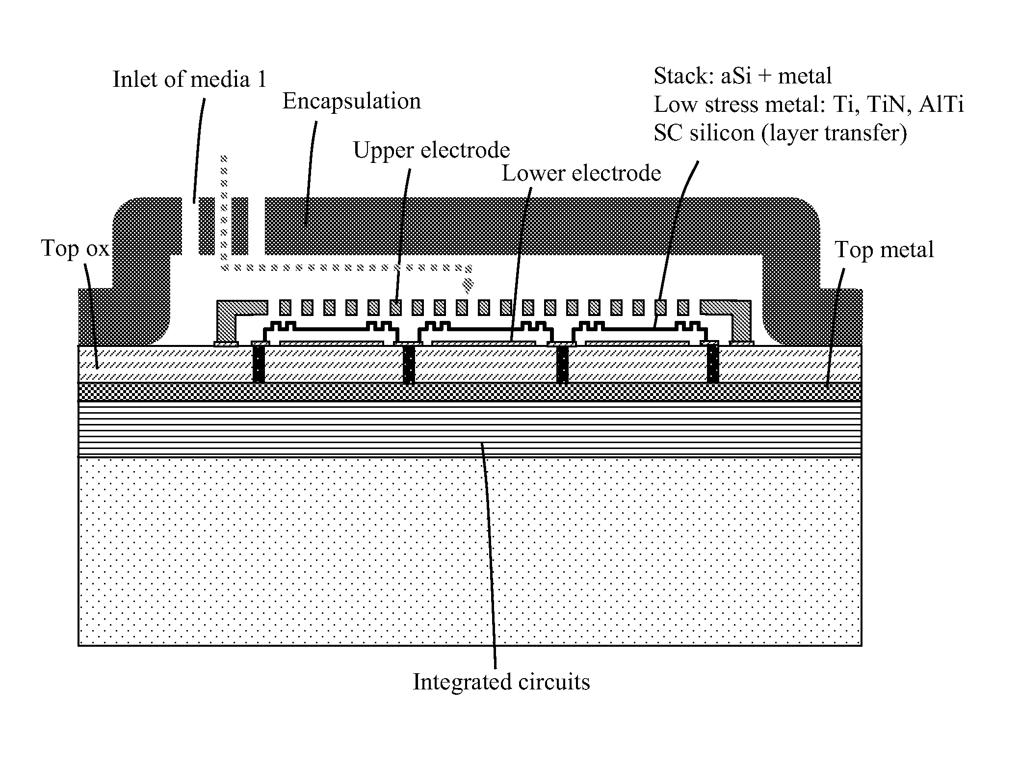
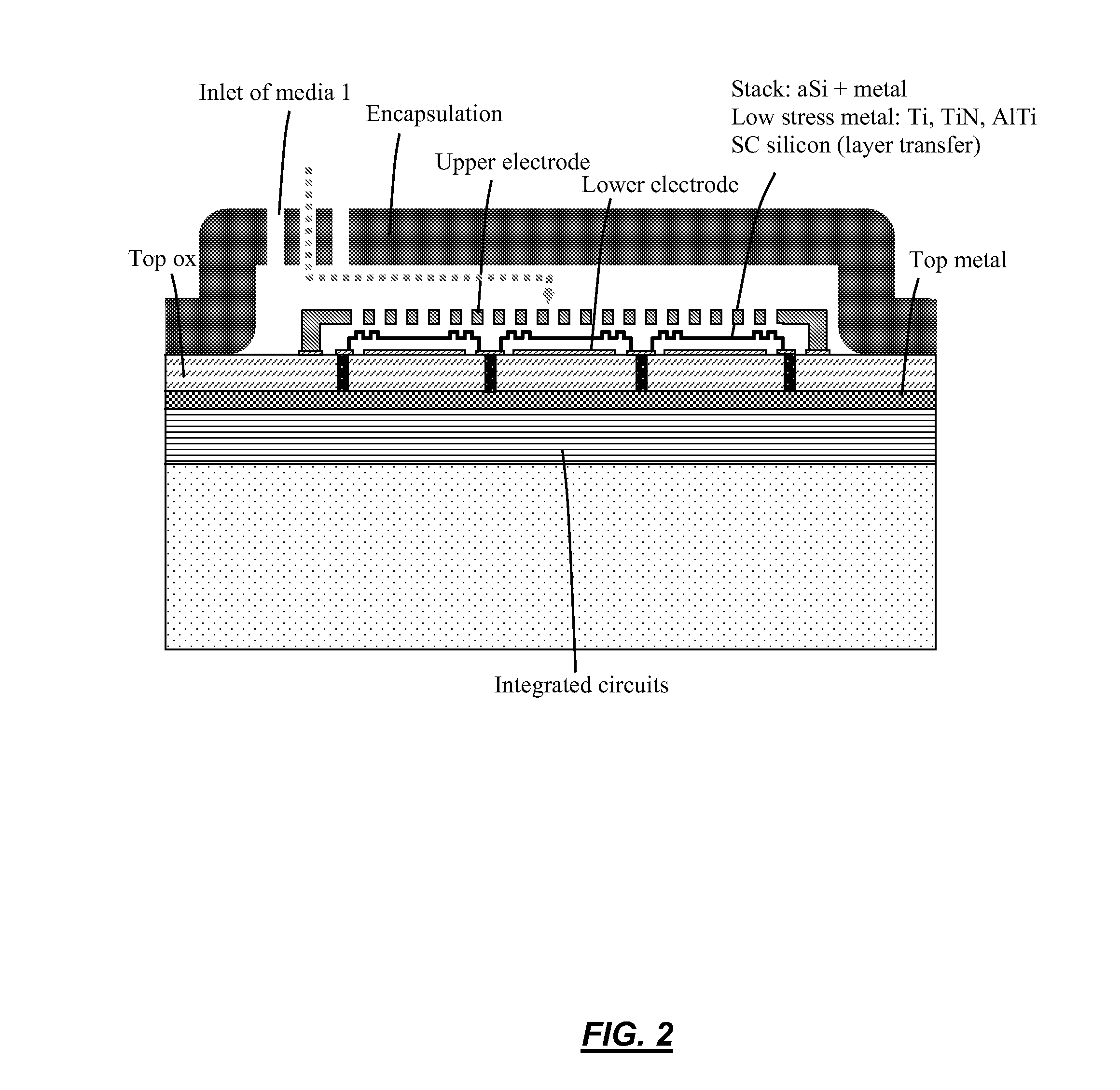
[0021]According to the present invention, techniques related generally to integrated micromachined and integrated circuit devices are provided. More particularly, the present invention provides a sensing device integral with integrated circuits, such as CMOS integrated circuits, which are foundry compatible. Merely by way of example, the present invention can be applied to a variety of applications, such as consumer, security, industrial, and medical.

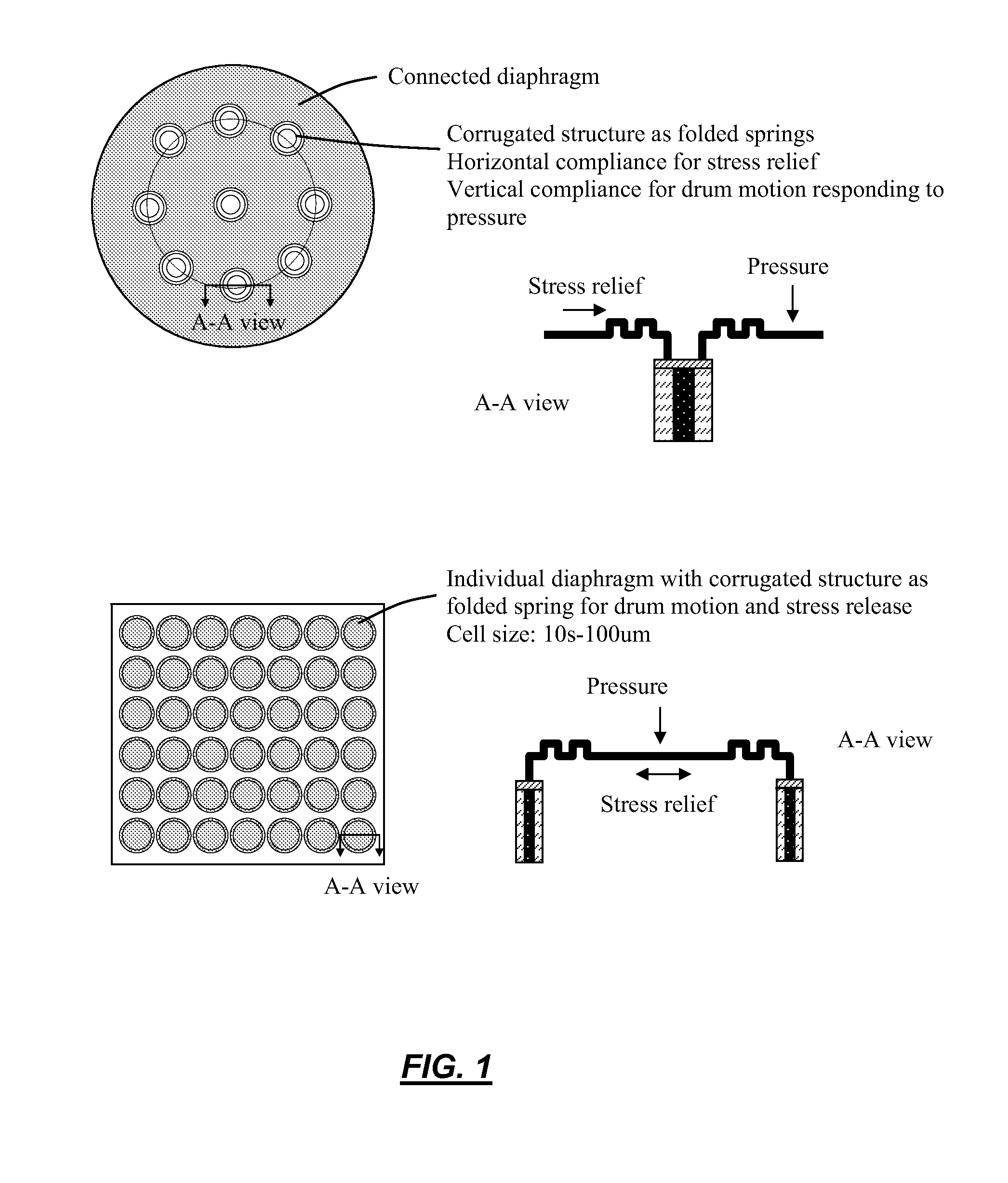
[0022]FIG. 1 is a simplified diagram of components of a micromachined pressure sensor according to one embodiment of the present invention. As depicted, the diaphragm is either a continuous layer or an array of smaller diaphragm cells. To obtain high sensitivity of the microphone, a large and thin diaphragm is essential. It is, however, difficult to achieve due to intrinsic stress of the diaphragm film. As shown in the cross section view, a corrugated structure is adopted as folded springs. The folded spring has a horizontal compliance ...


PUM


Abstract

A monolithically integrated MEMS pressure sensor and CMOS substrate using IC-Foundry compatible processes. The CMOS substrate is completed first using standard IC processes. A diaphragm is then added on top of the CMOS. In one embodiment, the diaphragm is made of deposited thin films with stress relief corrugated structure. In another embodiment, the diaphragm is made of a single crystal silicon material that is layer transferred to the CMOS substrate. In an embodiment, the integrated pressure sensor is encapsulated by a thick insulating layer at the wafer level. The monolithically integrated pressure sensor that adopts IC foundry-compatible processes yields the highest performance, smallest form factor, and lowest cost.

Description

CROSS-REFERENCES TO RELATED APPLICATIONS[0001]This application claims priority to U.S. Provisional Patent Application No. 61 / 079,110, filed Jul. 8, 2008, U.S. Provisional Patent Application No. 61 / 079,112, filed Jul. 8, 2008, U.S. Provisional Patent Application No. 61 / 079,113, filed Jul. 8, 2008, U.S. Provisional Patent Application No. 61 / 079,115, filed Jul. 8, 2008, U.S. Provisional Patent Application No. 61 / 079,116, filed Jul. 8, 2008, U.S. Provisional Patent Application No. 61 / 079,117, filed Jul. 8, 2008, U.S. Provisional Patent Application No. 61 / 084,223, filed Jul. 28, 2008, and U.S. Provisional Patent Application No. 61 / 084,226, filed Jul. 28, 2008, all of which are commonly owned and are incorporated in their entirety herein by reference for all purposes.STATEMENT AS TO RIGHTS TO INVENTIONS MADE UNDER FEDERALLY SPONSORED RESEARCH AND DEVELOPMENT[0002]NOT APPLICABLEREFERENCE TO A “SEQUENCE LISTING,” A TABLE, OR A COMPUTER PROGRAM LISTING APPENDIX SUBMITTED ON A COMPACT DISK[00...

Claims


Application Information

Patent Timeline
Patent Type & Authority Applications(United States)
IPC IPC(8): H01L29/84H01L21/30
CPCB81B2201/0264B81C1/00246B81C2201/0192G01L9/0042G01L9/0054G01L9/0073
Inventor YANG, XIAO, CHARLES
Owner MOVELLA INC
Why Eureka
Try Eureka