Lock snap structure of slide rail

a technology of locking snap and slide rail, which is applied in the direction of drawers, furniture parts, domestic applications, etc., can solve the problems of easy breakage of release tab 49, easy detachment of entire drawers, and easy falling down due to unintentional touching, etc., and achieves convenient manufacturing and assembly. , the effect of simple construction

Inactive Publication Date: 2002-04-23
KING SLIDE WORKS CO LTD
View PDF3 Cites 76 Cited by
  • Summary
  • Abstract
  • Description
  • Claims
  • Application Information

AI Technical Summary

Benefits of technology

The primary objective of the present invention is to provide a lock snap structure of a slide rail which has a simple construction, so that the slide rail may be manufactured and assembled conveniently.
A secondary objective of the present invention is to provide a lock snap structure of a slide rail, wherein the drawer may be detached easily, and the lock snap structure may have an exact snap lock function without incurring the problem of unintentional touching.
Another objective of the present invention is to provide a lock snap structure of a slide rail, wherein the slide rail may be positioned when it is pulled to the maximum length, so that the slide rail will not retract due to slight touch of an external force.
In accordance with the present invention, there is provided a lock snap structure of a slide rail comprising: an inner rail, having a face provided with at least one first locking plate and at least one second locking plate, a locking groove defined between the first locking plate and the second locking plate, adjacent ends of the first locking plate and the second locking plate having a greater height, each of the first locking plate and the second locking plate formed with a slope which is inclined and lowered from the adjacent end toward the other end; an outer rail mounted on the inner rail, the outer rail provided with a retaining plate, the retaining plate formed with at least one protruding guide block, the guide block capable of climbing and rising along the slope of the first locking plate and the second locking plate of the inner rail to enter the locking groove between the first locking plate and the second locking plate; and a drawing plate, mounted between the inner rail and the outer rail, and moved in a longitudinal direction, one end of the drawing plate capable of being pulled, the other end of the drawing plate being pulled by one end of an elastic member, the other end of the elastic member being hooked on the inner rail, such that the drawing plate can be returned to its original position, the drawing plate formed with a slot hole to allow protrusion of the first locking plate and the second locking plate of the inner rail, the slot hole of the drawing plate formed with at least one guide plate, the guide plate having two sides each formed with an oblique shoulder, the oblique shoulder of the guide plate capable of pressing the guide block of the retaining plate when the drawing plate is moved, so that the guide block may detach from the locking groove between the first locking plate and the second locking plate of the inner rail.

Problems solved by technology

However, all of the above-mentioned prior arts have a complicated construction.
In addition, the entire drawer is easily detached to fall down due to touching unintentionally.
Especially, in one of the above-mentioned prior art, the release tab 49 is easily broken due to an external hit.

Method used


Image

  • Lock snap structure of slide rail
  • Lock snap structure of slide rail
  • Lock snap structure of slide rail

Examples


Embodiment Construction

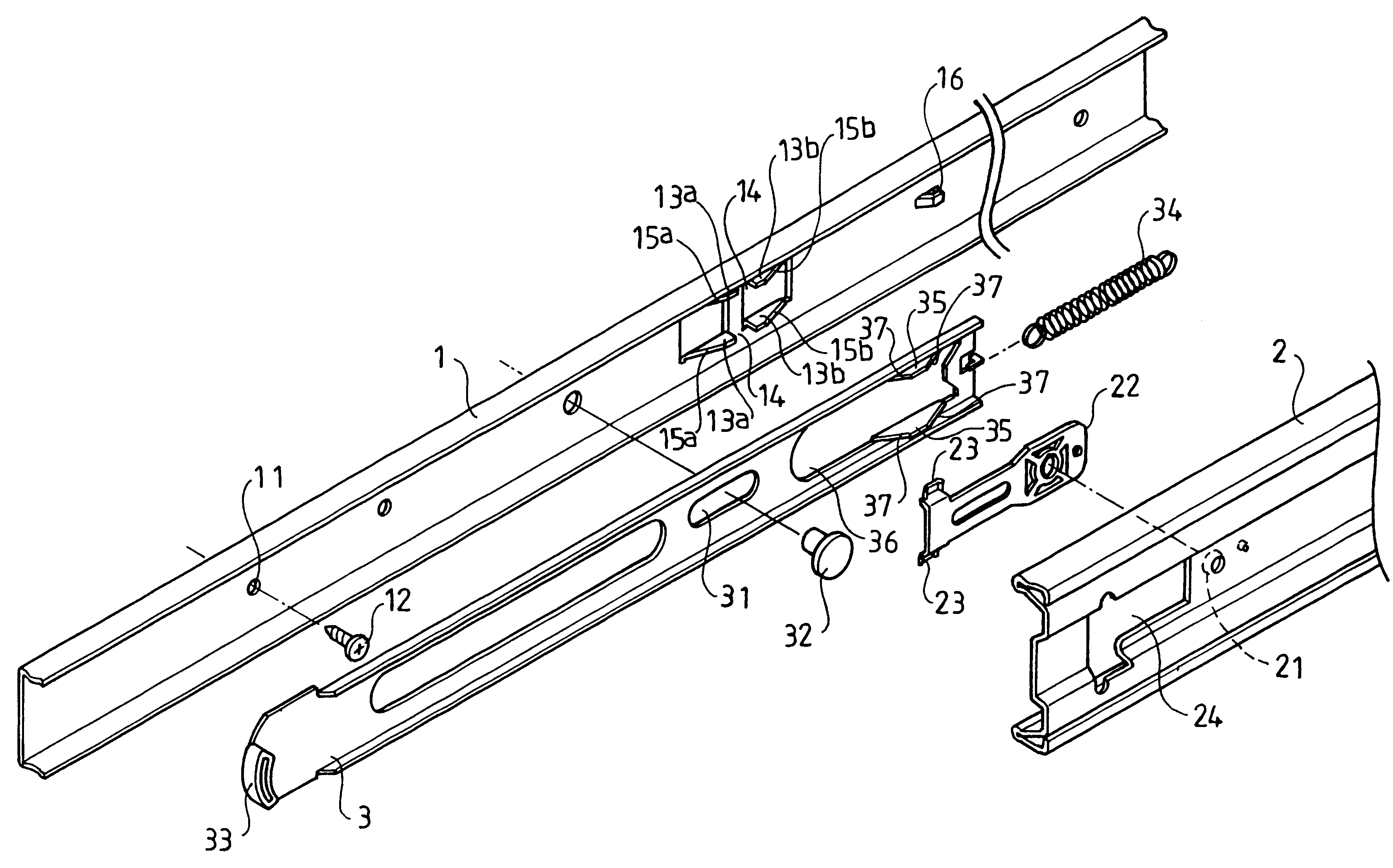
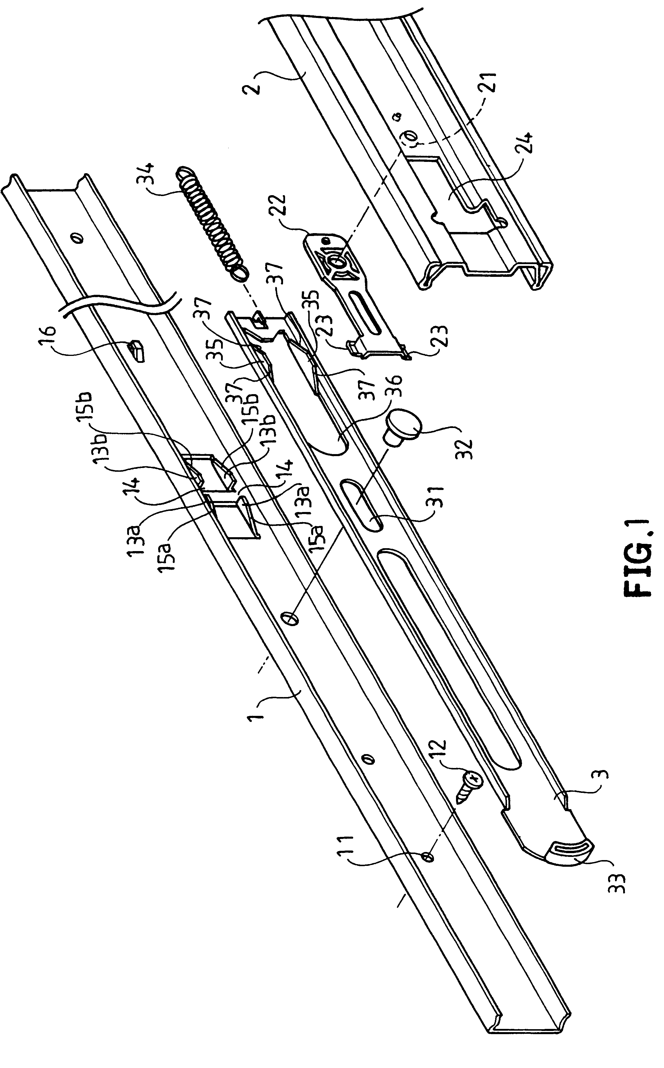
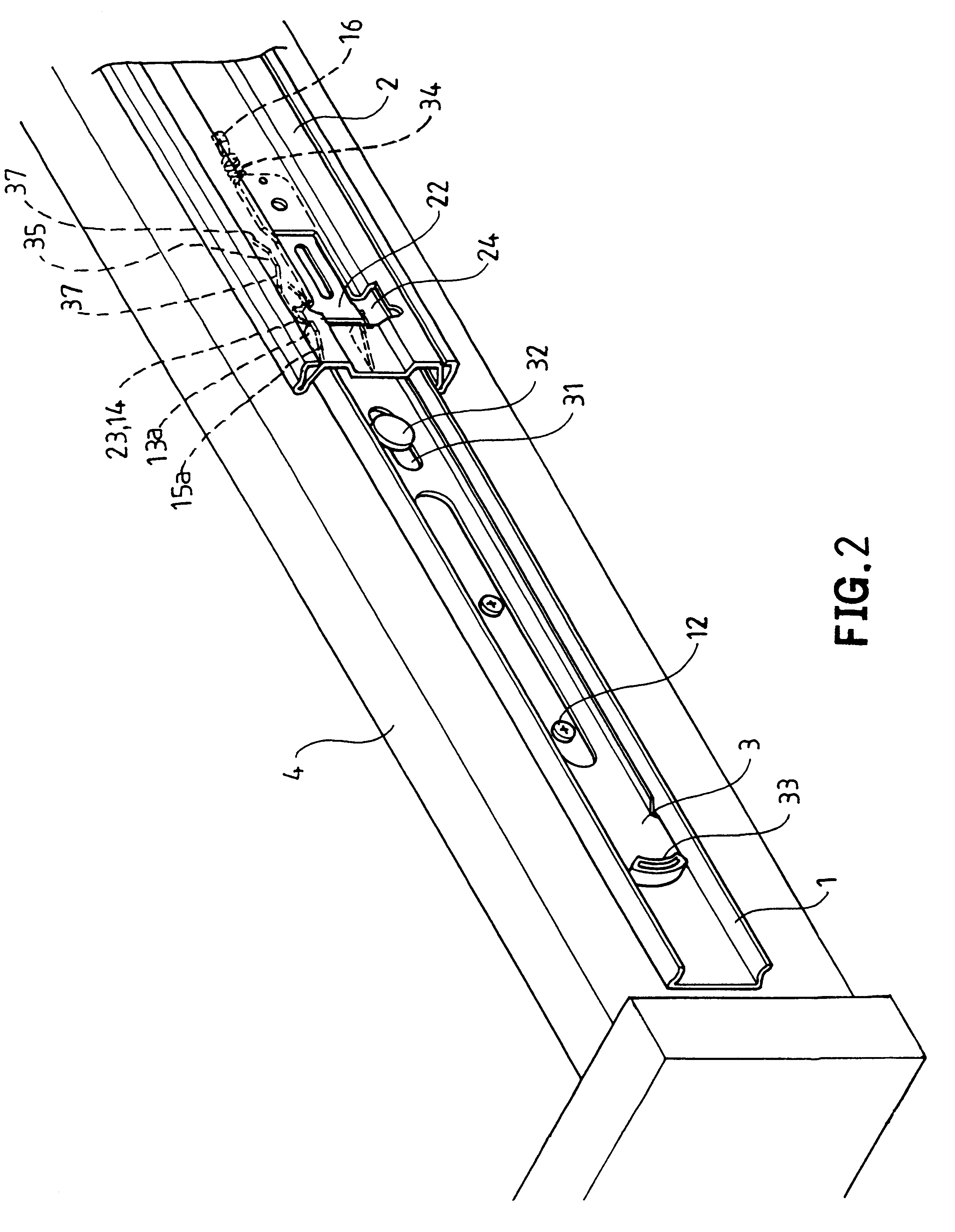
Referring to the drawings and initially to FIG. 1, a lock snap structure of a slide rail in accordance with the preferred embodiment of the present invention comprises an inner rail 1, an outer rail 2, and a drawing plate 3.

The inner rail 1 defines positioning holes 11, so that the inner rail 1 my be fixed on the two sides of a drawer by positioning members 12. The inner rail 1 is formed with two opposite first locking plates 13a, and two opposite second locking plates 13b directed toward the outer rail 2. The first locking plate 13a and the second locking plate 13b are adjacent and symmetric with each other. The adjacent ends of the first locking plate 13a and the second locking plate 13b have a greater protruding height, and a locking groove 14 is defined between the first locking plate 13a and the second locking plate 13b each of the first locking plate 13a and the second locking plate 13b is formed with a slope 15a and 15b which is inclined and lowered from the position having a...


PUM


Abstract

A lock snap structure of a slide rail includes an inner rail provided with two adjacent locking plates and a locking groove between the two locking plates. Each locking plate is formed with a slope. An outer rail mounted on the inner rail is provided with a retaining plate which has a guide block which may move along the slope of the locking plates to enter the locking groove. A drawing plate mounted between the inner rail and the outer rail has a first end that may be pulled and a second end pulled by an elastic member. The drawing plate has a slot hole provided with a guide plate which has an oblique shoulder that may press the guide block when the drawing plate is moved, so that the guide block may detach from the locking groove between the locking plates.

Description

BACKGROUND OF THE INVENTION1. Field of the InventionThe present invention relates to a lock snap structure of a slide rail, and more particularly to a slide rail used to guide a drawer or the support rack of a keyboard of a computer table. When the slide rail is assembled, it has a snap effect for preventing automatic detachment. In addition, the slide rail may be dismantled conveniently.2. Description of the Related ArtA conventional slide rail in accordance with the prior art shown in FIG. 8 may be used to guide a drawer or the support rack of a keyboard of a computer table, and primarily comprises an inner rail 91, an outer rail 92, and an intermediate rail 93. The inner rail 91 is provided with a pivotable locking member 94 whose terminal end may be rested on a stop block 95 mounted on the outer rail 92 or the intermediate rail 93, thereby preventing detachment of a drawer that is combined on the inner rail 91. When the user wishes to remove the drawer, the locking member 94 may...

Claims


Application Information

Patent Timeline
Patent Type & Authority Patents(United States)
IPC IPC(8): A47B88/04A47B88/08A47B88/49
CPCA47B88/08A47B2210/0016A47B88/49
Inventor LIN, TSUNG-LUNGHWANG, SHIH-LONGWANG, CHUN-CHIANG
Owner KING SLIDE WORKS CO LTD
Why Eureka
Try Eureka