Tool holder assembly

Inactive Publication Date: 2002-04-23
FL TOOLHOLDERS
View PDF5 Cites 20 Cited by
  • Summary
  • Abstract
  • Description
  • Claims
  • Application Information

AI Technical Summary

Benefits of technology

In order to prevent rocking of the chuck relative to the spindle, a piston having a conical surface coaxial with the axis of the spindle is mounted to the spindle at the innermost end of the spindle bore. This piston is axially movable between a first and second position in which the first position is closer to the open end of the spindle bore than the second position. A helical compression spring urges the piston towards its first position while a fastener extending through the piston limits the axial movement of the piston as well as maintains the piston coaxial with the axis of the spindle.

Problems solved by technology

A primary disadvantage, however, of the previously known toolholder assemblies utilizing a ball lock is that the ball lock provides a less secure attachment between the chuck and the spindle than obtainable by the previously known threaded collar locking arrangements.
Consequently, these previously known toolholder assemblies utilizing a ball lock have been known to rock slightly during machining operations.

Method used


Image

  • Tool holder assembly
  • Tool holder assembly
  • Tool holder assembly

Examples


Embodiment Construction

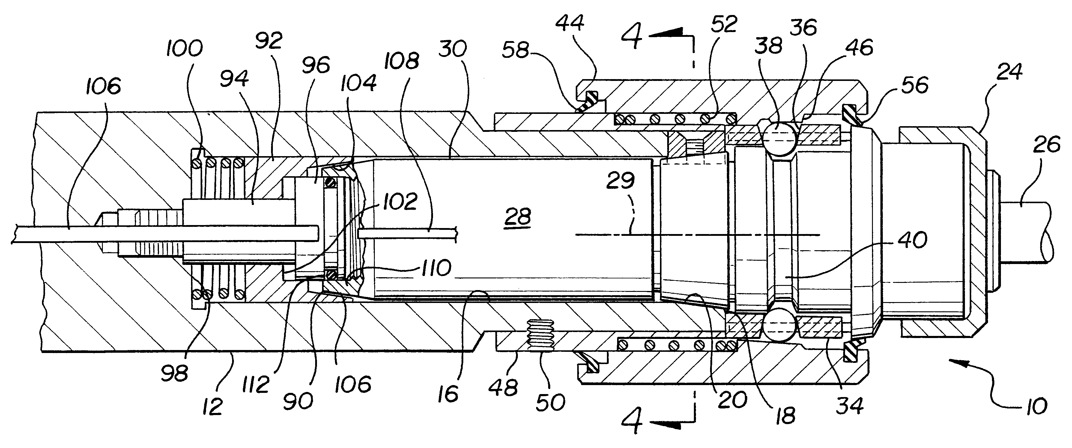
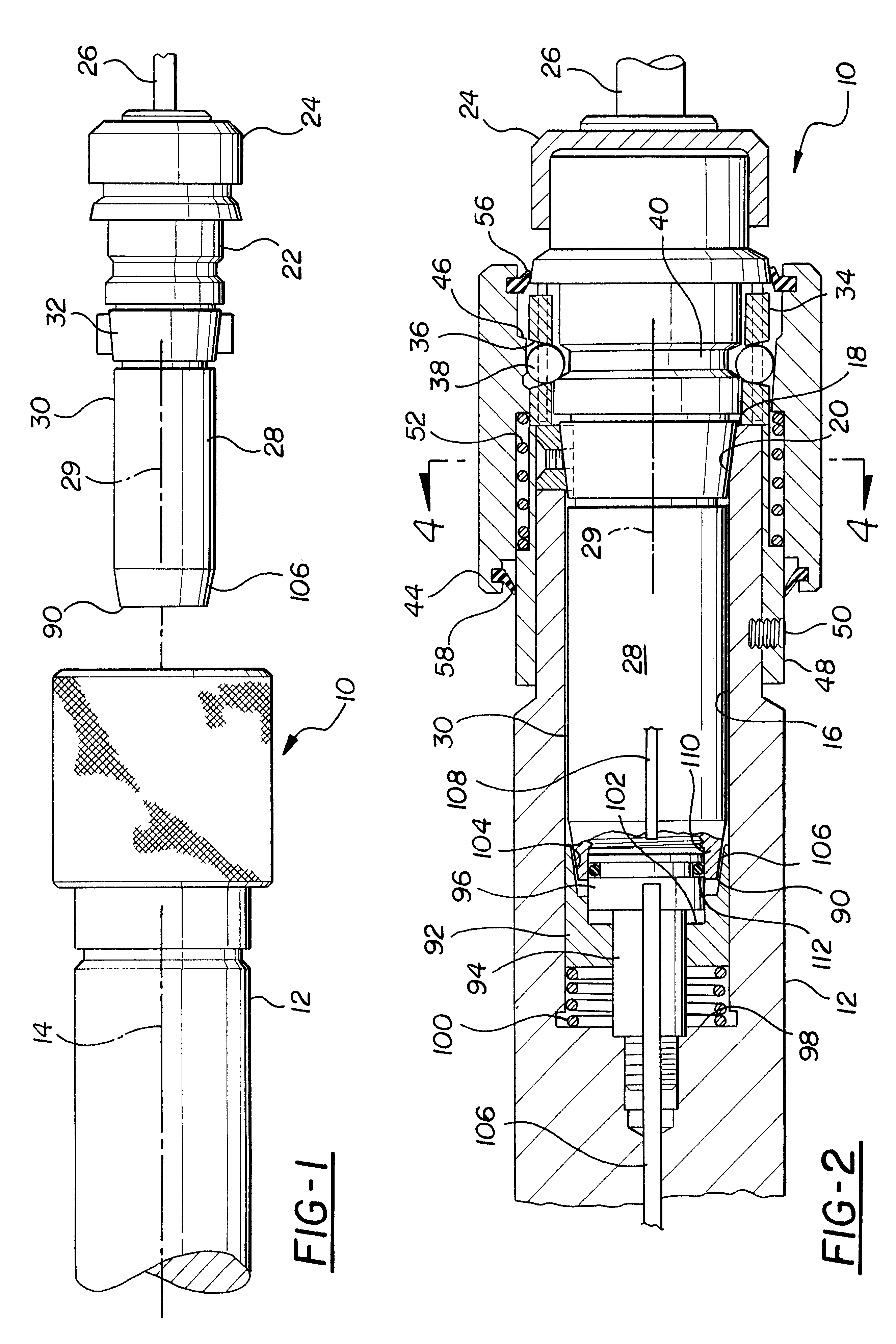
With reference first to FIGS. 1-3, a preferred embodiment of the toolholder assembly 10 of the present invention is there shown and comprises a spindle 12 adapted to be rotatably driven about its longitudinal axis 14. The spindle 12 includes a longitudinally extending bore 16 open at one end 18 of the spindle 12. Preferably, the spindle bore 16 is generally cylindrical in shape and includes an outwardly flared conical surface 20 adjacent the end 18 of the spindle 12.

Referring now particularly to FIGS. 1 and 2, the toolholder assembly 10 further comprises a chuck 22 having a collet 24, or other conventional means, for coaxially securing a tool 26 to the chuck 22.

The chuck 22 includes an elongated shank 28 dimensioned for insertion into the spindle bore 16 to an operative position, as illustrated in FIG. 2. Consequently, the shank 28 includes a generally cylindrical portion 30 as well as a conical portion 32 complementary to the conical surface 20 on the spindle bore 16. Furthermore, ...


PUM

PropertyMeasurementUnit
Shapeaaaaaaaaaa
Resilienceaaaaaaaaaa

Abstract

A toolholder assembly is disclosed having an elongated spindle adapted to be rotatably driven about a longitudinal axis. The spindle also includes a longitudinally extending bore open at one end. A chuck has a collet at one end for holding a tool and an elongated shank at its other end adapted for insertion into the spindle bore. A ball lock assembly releasably coaxially secures the chuck to the spindle upon insertion of the chuck shank into the spindle bore to an operable position. The chuck also includes a conical surface at the free end of the shank. This free end of the shank engages a spring loaded piston positioned at the innermost end of the spindle bore when the chuck is inserted into the spindle to its operable position and this piston includes a conical surface complementary to the conical surface on the shank. The cooperation between the ball lock assembly and the piston coaxially and securely, but releasably, secures the chuck to the spindle.

Description

I. Field of the InventionThe present invention relates generally to toolholder assemblies and, more particularly, to a quick release toolholder assembly.II. Description of the Prior ArtThere are many previously known toolholders of the type used in manufacturing operations. These toolholders typically comprise a chuck having a collet for securing a tool, such as a drill, reamer or the like, coaxially to the chuck. The chuck, in turn, includes an elongated shank which is inserted into a receiving bore on a rotatably driven spindle. The spindle bore is coaxial with the axis of rotation of the spindle so that, in the ideal situation, the tool secured by the collet to the chuck is coaxial with the axis of rotation of the spindle.In one type of previously known toolholder assembly, cooperating conical surfaces are formed on both the chuck shank as well as the spindle bore in order to center the axis of the chuck with the axis of the spindle. In other cases, however, both the spindle bore...

Claims


Application Information

Patent Timeline
IPC IPC(8): B23B31/10B23B31/107
CPCB23B31/1071Y10T408/95Y10T279/17752Y10T409/309408
Inventor GAUDREAU, JACK R.BLEAU, TERRY R.CHALMERS, JEFFREY L.
Owner FL TOOLHOLDERS
Why Eureka
Try Eureka