Stud for construction of seismic and fire resistant shaft walls

a technology for seismic and fire resistance, applied in the direction of girders, walls, joists, etc., can solve the problems of obstructing the user's ability to attach the opposite wall board, the paquette suffers from the same limitation as a conventional sheet metal stud, and the screw driver or screw gun cannot be inserted into the channel formed, etc., to achieve the effect of convenient installation, increased time and labor, and cheaper selling price to consumers

Inactive Publication Date: 2002-05-07
HERREN THOMAS ROSS
View PDF15 Cites 53 Cited by
  • Summary
  • Abstract
  • Description
  • Claims
  • Application Information

AI Technical Summary

Benefits of technology

The stud for construction of seismic and fire resistant shaft wall assemblies claimed herein permits construction of the shaft wall assembly strictly from within the shaft cavity as a result of the incongruence of the length of the anterior and posterior flanges which transversely depend from the vertical web of the stud thereby forming a generally J-shape cross-section. The incorporation of an elongated posterior flange in relation to the anterior flange allows the user to attach the interior shaft wallboard to the exterior side of the posterior flange from the anterior of the claimed stud. The incongruence between the posterior flange and anterior flange permits the user to insert a screw driver or screw gun into the channel formed between the flanges to securely attach the interior wall of the shaft wall assembly. If the posterior flange and anterior flange are substantially the same length, the user cannot secure the posterior flange to the wallboard which forms the exterior wall of the shaft cavity from the anterior side of the stud because the anterior flange obstructs the insertion of a nail gun or screw driver between the flanges to attach the interior wall board to the posterior flange. Consequently, if the anterior flange and posterior flange are substantially the same length, as found in the prior art, the interior shaft wallboard must be installed from both inside and outside the shaft cavity thereby requiring additional time and labor.
The incorporation of slots in the posterior flange through which the interior wall board is attached permits the wallboard to deflect horizontally as a result of physical forces such as earthquakes and wind sway. The ability of the wallboard to deflect horizontally during physical forces serves to protect the physical integrity of the wallboard against cracking. The existence of cracks in the wall compromises the wall assembly's ability to resist the passage of fire, smoke and hot gases from the shaft cavity into the remainder of the building in the event of a fire. It is accordingly, an object of the invention to provide a stud for construction of a shaft wall assemblies which meets required safety standards for fire, wind loading and seismic forces set forth in current building codes, such as the Uniform Building Code.
It is an additional object to provide a stud for the construction of a cavity shaft wall which is relatively inexpensive, lightweight, and relatively easy to install. In comparison to the prior art, the claimed stud only requires four folds and less raw material for its construction which results in a cheaper selling price to consumer.
These and other objects and advantages of the invention will be more readily apparent when considered in relation to the preferred embodiments of the invention as set forth in the specification and shown in the drawings.

Problems solved by technology

The opposite flange possessing the same length as the near flange obstructs the users ability to attach the opposite wall board.
Consequently, screw drivers or screw guns cannot be inserted into the channel formed between the equal size flanges depending from the stud web to attach the wallboard located on the side opposite from the user without the user being positioned on the same side as the wallboard to complete the installation.
Likewise, the slotted channel claimed in U.S. Pat. No. 5,127,203, issued to Robert Paquette suffers from the same limitation as a conventional sheet metal stud.
The requirement of the pop-up tab requires additional labor and cost to manufacture the pop-up tabs by forming the pop-ups by hand or using a specially designed die.
Furthermore, the incorporation of the pop-up tabs in U.S. Pat. Nos. 4,866,899, 4,364,212 and 3,940,899 compromises the strength of the stud.
In addition, U.S. Pat. Nos. 4,866,899, 4,364,212 and 3,940,899 do not provide a means or method for the construction of shaft wall with the ability to withstand seismic and wind sway movement.
U.S. Pat. No. 6,047,508 issued to Goodman is limited to the construction of a moveable wall panel with rigid frame.
The "G-shaped" structure disclosed in the Goodman Patent (element 51) does not provide for movement of the attached wallboard, nor does it permit the user to attach opposing wallboard elements from one side.
If the posterior flange and anterior flange are substantially the same length, the user cannot secure the posterior flange to the wallboard which forms the exterior wall of the shaft cavity from the anterior side of the stud because the anterior flange obstructs the insertion of a nail gun or screw driver between the flanges to attach the interior wall board to the posterior flange.
Consequently, if the anterior flange and posterior flange are substantially the same length, as found in the prior art, the interior shaft wallboard must be installed from both inside and outside the shaft cavity thereby requiring additional time and labor.
The existence of cracks in the wall compromises the wall assembly's ability to resist the passage of fire, smoke and hot gases from the shaft cavity into the remainder of the building in the event of a fire.

Method used


Image

  • Stud for construction of seismic and fire resistant shaft walls
  • Stud for construction of seismic and fire resistant shaft walls
  • Stud for construction of seismic and fire resistant shaft walls

Examples


second embodiment

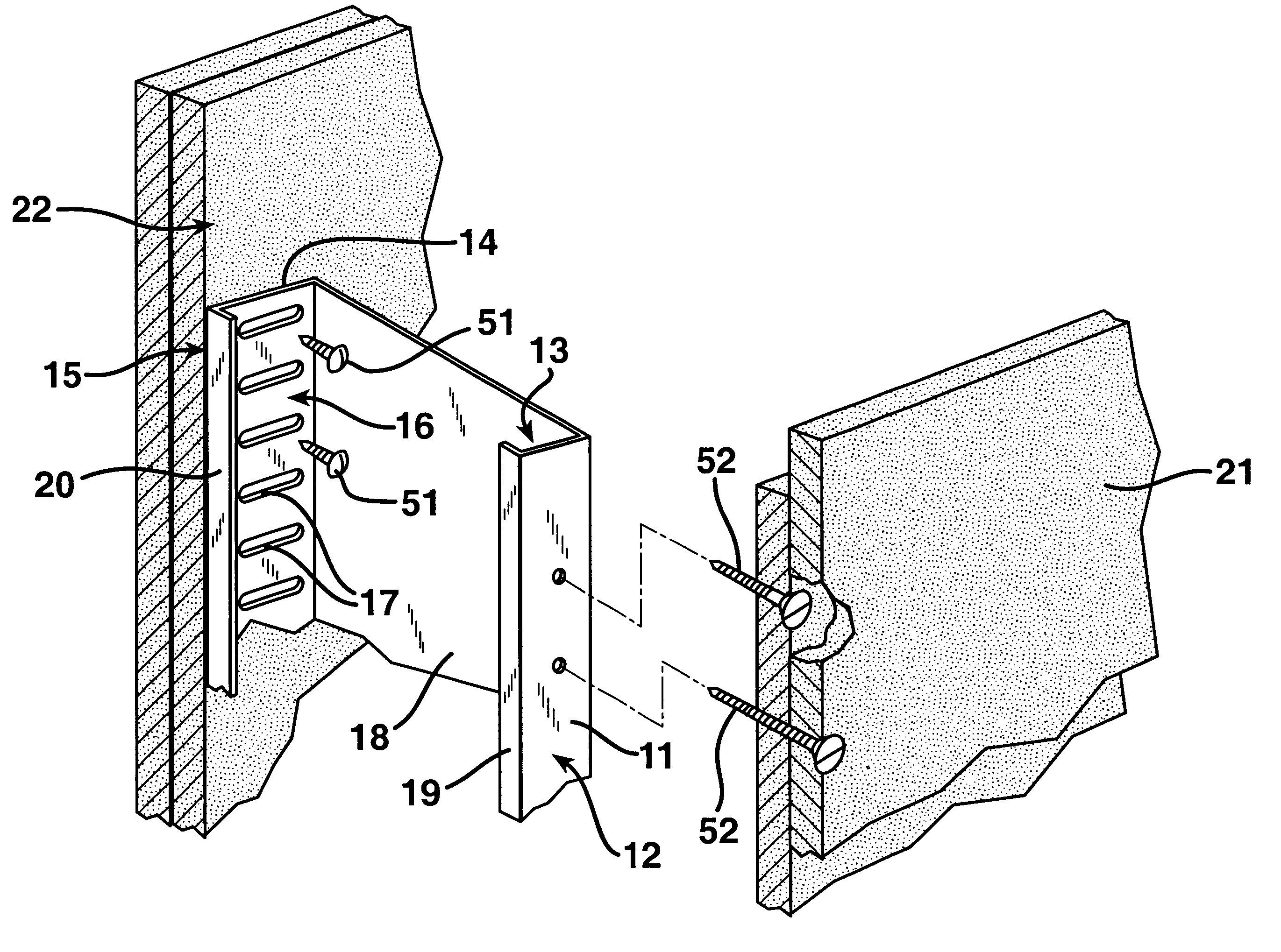
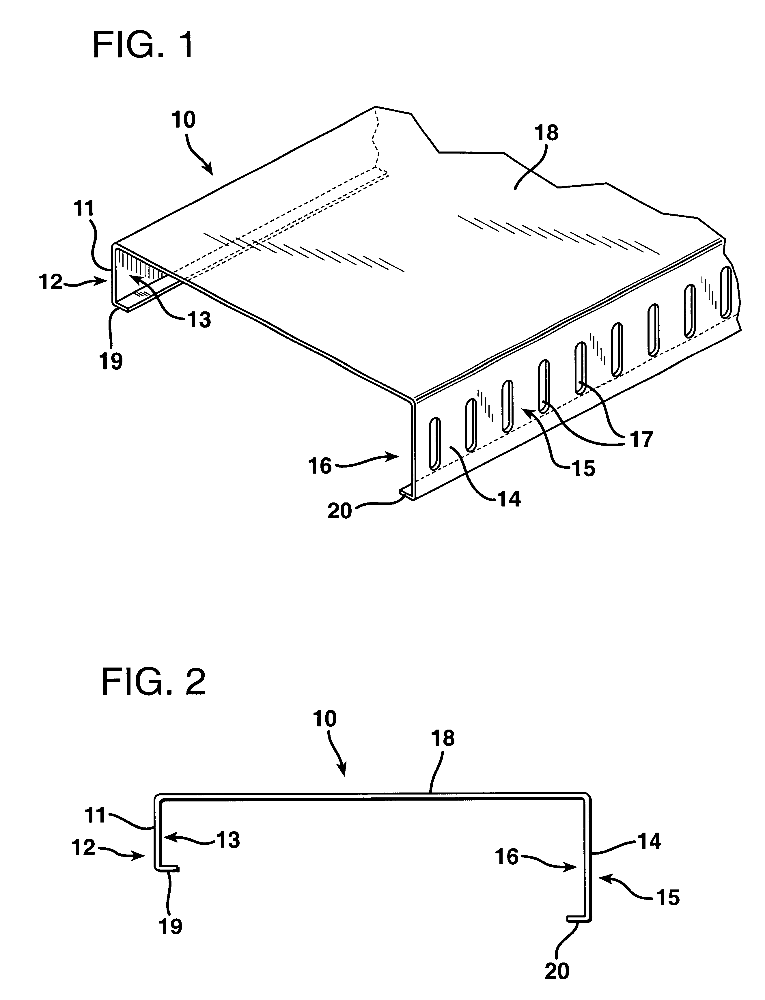
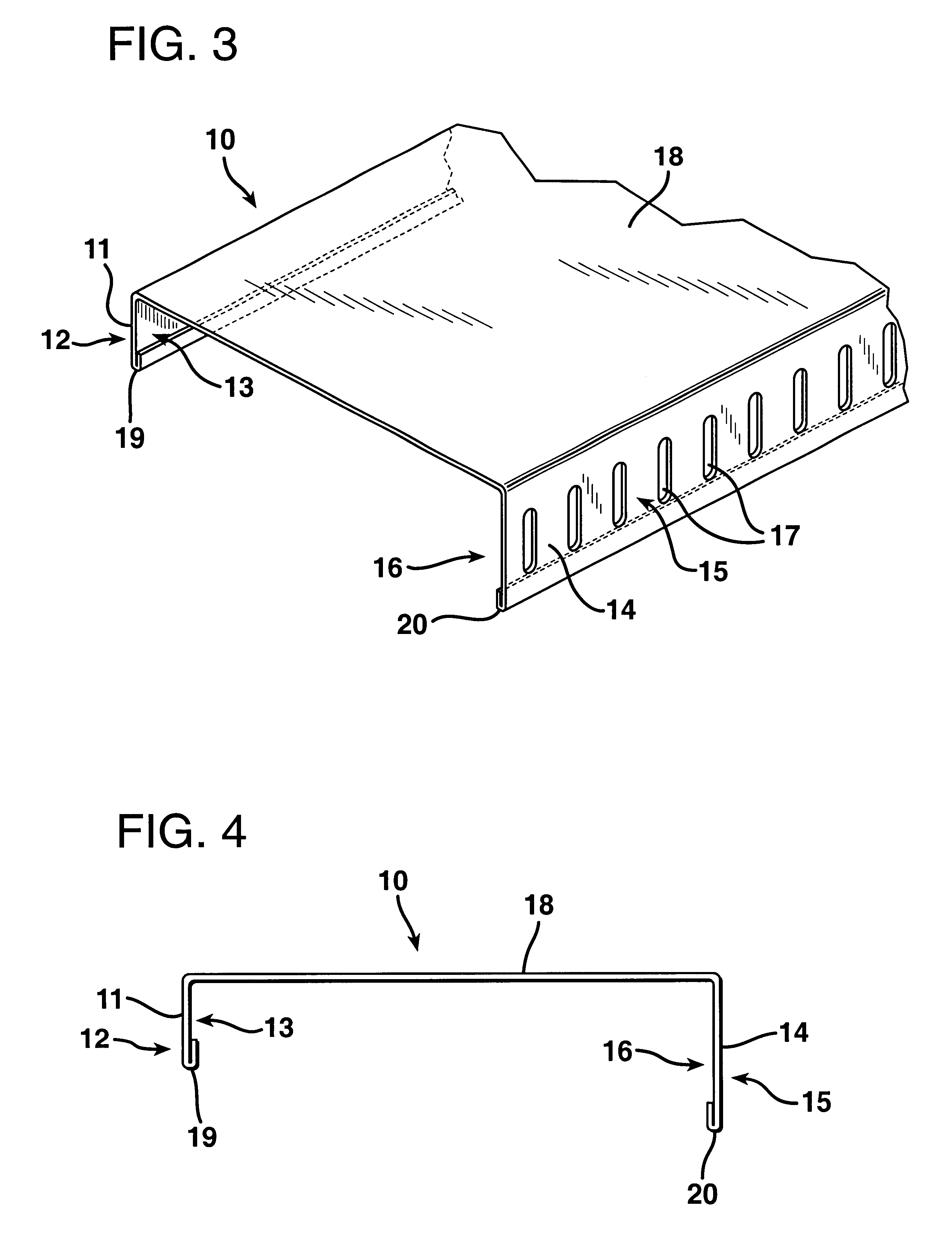
this invention is depicted in FIGS. 3 and 4. The addition of stiffening lips 19, 20 anterior flange 11 and posterior flange 14 is recommended to strengthen the rigidity of the flanges. The stiffening lips are formed on the distal portion of the posterior flange and the distal portion of the anterior flange. The preferred width of the anterior flange stiffening lip 19 is 0.31 centimeters (1 / 8 of an inch) and the preferred length of the posterior flange lip 20 is 1.58 centimeters (5 / 8 of an inch). The stiffening lips 19,20 may depend perpendicularly from the anterior and posterior flanges 11, 14 into the channel formed between the flanges. It is preferred that the stiffening lip is bent acutely inward and parallel with the flange thereby not encroaching upon the useable space between anterior flange 11 and posterior flange 14 for the insertion of a screw driver or screw gun to attach the exterior shaft cavity wallboard 22 to the posterior flange 14. If perpendicular stiffening lip are...


PUM


Abstract

A stud for construction of fire resistant and seismic resistant shaft walls (10), including but not limited to elevator shafts and stairwells. The claimed metal stud is used for constructing shaft wall assemblies which can withstand vertical, and horizontal movements due to seismic forces, wind sway, and inter-story drift resulting from gravity and the rotation of the earth. This stud comprises: an anterior flange (11); posterior flange (14) which is longer than the anterior flange (11) possessing a plurality of parallel horizontal fastening slots (17) along the length of the posterior flange (14); and a vertical web (18) connecting the anterior flange (11) and posterior flange (14) in parallel forming a generally J-shaped channel. The longer posterior flange with fastener slots permits the construction if the shaft wall assembly solely from within the shaft cavity.

Description

BACKGROUND OF THE INVENTIONField of the InventionThe present invention relates to metal framing construction, and more particularly to a stud for the construction of fire-resistant and seismic resistant shaft walls, i.e., elevator shafts and stairwells, from completely within the shaft cavity.SUMMARY OF THE INVENTIONThe present invention discloses a stud for construction of seismic and fire resistant shaft walls, including but not limited to elevator shafts and stair wells, comprising a vertical web with incongruent anterior and posterior flanges depending therefrom, and multiplicity of horizontal slots incorporated in the posterior flange.DESCRIPTION OF PRIOR ARTThis invention is an improvement over the prior art based upon the ease manufacturing the claimed stud and the ease of constructing a shaft wall assembly strictly from inside the shaft cavity, using the method disclosed in U.S. Pat. No. 5,950,385. Construction of seismic resistant and fire resistant shaft wall assemblies us...

Claims


Application Information

Patent Timeline
Patent Type & Authority Patents(United States)
IPC IPC(8): E04C3/07E04B2/74E04C3/04E04F17/00E04F13/08
CPCE04B2/7457E04C3/07E04F17/005E04B2/7411E04C2003/0434E04C2003/0473E04F13/0803E04C2003/0421
Inventor HERREN, THOMAS ROSS
Owner HERREN THOMAS ROSS
Why Eureka
Try Eureka