
Apparatus for controlling work feed rate for cutting wood, metal and other materials

a technology of bandsaw machine and feed rate, which is applied in the direction of program control, metal sawing accessories, instruments, etc., can solve the problems of erratic lateral movement of the saw blade, large waste, and the rate at which the work is fed into the saw blad

Inactive Publication Date: 2002-05-07
SMITH H REID
View PDF14 Cites 46 Cited by
  • Summary
  • Abstract
  • Description
  • Claims
  • Application Information

AI Technical Summary

Problems solved by technology

In the lumber industry, current production methods result in a larger than necessary amount of waste in order to manufacture finished dimension lumber.
The first problem is the rate at which the work is fed into the saw blade.
This automatic feed system permits overfeeding and in some cases underfeeding of the saw machine, resulting in erratic lateral movement of the saw blade and loss of control of the saw line.
The second problem is the target size of the rough sawn work, which must be maintained large enough so that finished lumber is not undersized.
This excess material, which is later removed to produce finish dimension lumber, represents waste.
Uncontrolled lateral deviations in the saw lines during the cutting operation require larger rough sawn target sizes.
These saw blade movements have several causes: misalignment of saw blade guides, normal saw blade tooth wear, bending or uneven dulling of saw teeth, and knots in the saw log.
These typical conditions can cause lateral instability of the saw blade, with resultant deviations of the saw line.
The third problem is offsetting of the saw blade from the desired saw line.
This ruins the saw blade tension, requiring hours of bench work to bring the saw back into proper tension so that it will again cut straight and accurately.
The saw blade could also disintegrate, destroying itself and surrounding equipment, thus requiring down time to repair the damage.
The safety of personnel is also placed in jeopardy if the saw blade disintegrates.
The fourth problem is the width of the saw cut, or kerf.
The fifth problem encompasses other considerations that directly affect optimized cutting efficiency, such as saw blade design, saw blade strain, and guide pressure.
This system works well in small bandsaw machines, but will not function adequately with the larger bandmill machines which have wider saw blades.
Large band saw machines have blade widths exceeding two inches, and the same problems exist with this patent as with the saw blade sagging angle control system.
However, using this system, once a slow-down step has been made, the speed remains slowed down for the entire length of a log or cant being sawn, which lowers production output.
This prior art does not address variable conditions within the same work piece, such as a log wherein the sawing conditions may vary significantly from one end to another, for example, from the butt end to the top end, as they relate to material density, sap rings, moisture content and even temperature.
In addition, my prior U.S. Pat. No. 4,644,832, does not take into consideration changes in zero reference signals which can change, in a 2-hour period, as much as 0.020 inches as a result of wear during cutting.
Finally, this prior art patent utilizes only processed signals, and in the event of significant lateral deviation of the saw blade, the prior art system does not react quick enough to prevent damage to the saw blade and / or the work piece because of the processing time required to condition the signals.

Method used


Image

  • Apparatus for controlling work feed rate for cutting wood, metal and other materials
  • Apparatus for controlling work feed rate for cutting wood, metal and other materials
  • Apparatus for controlling work feed rate for cutting wood, metal and other materials

Examples


Embodiment Construction

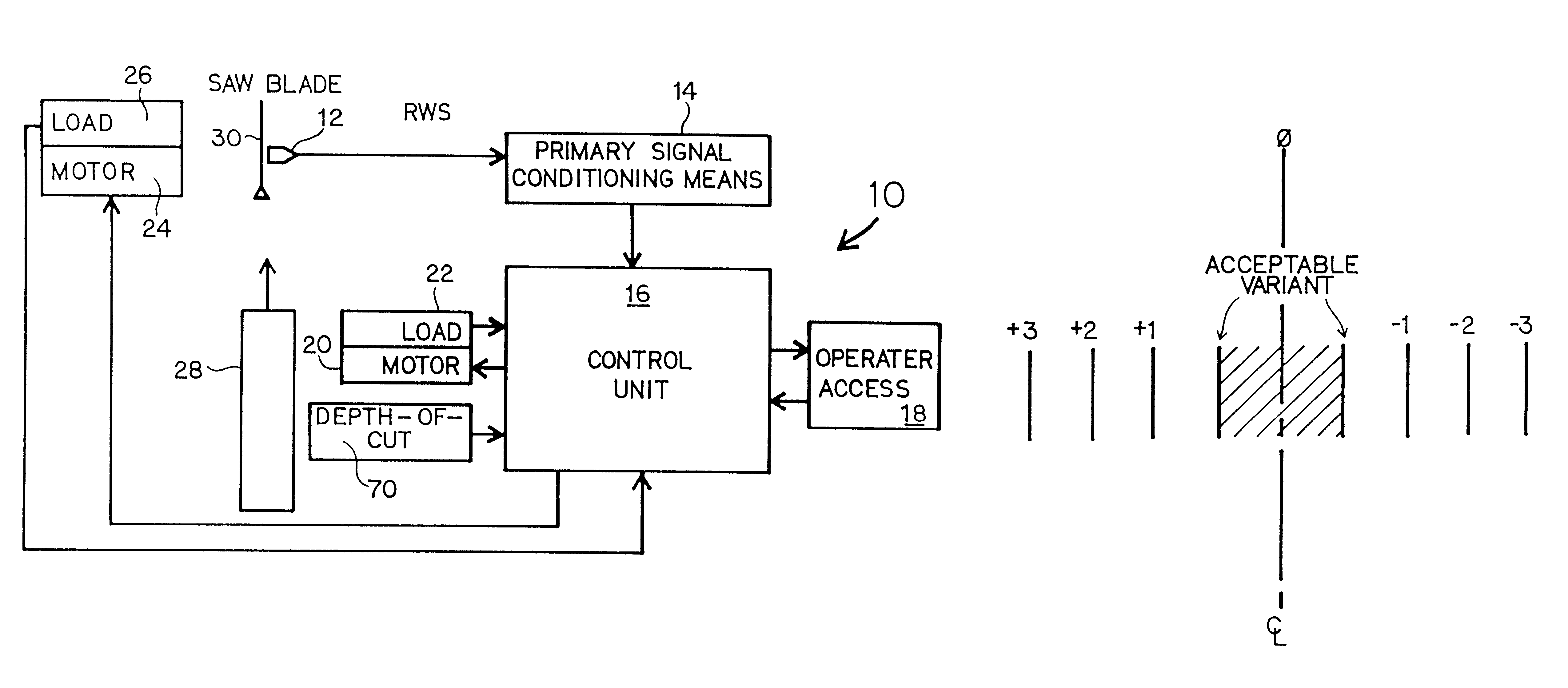
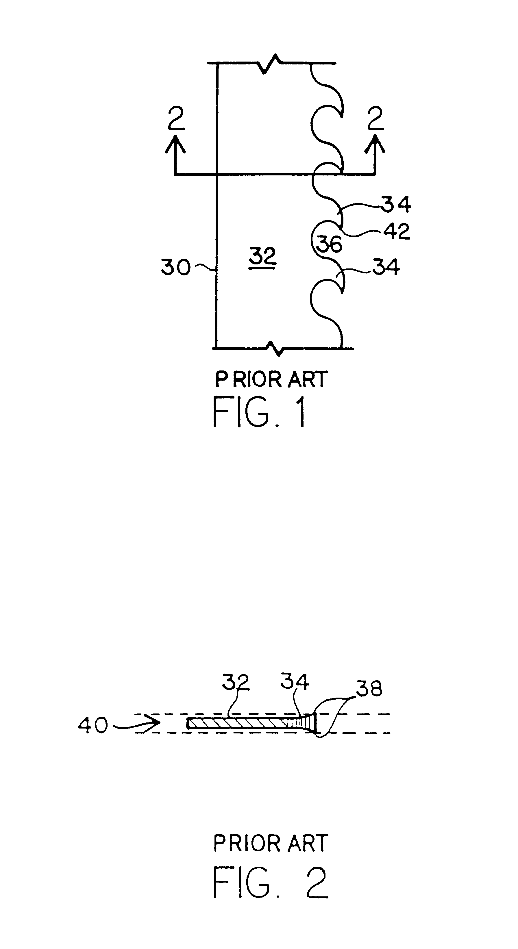
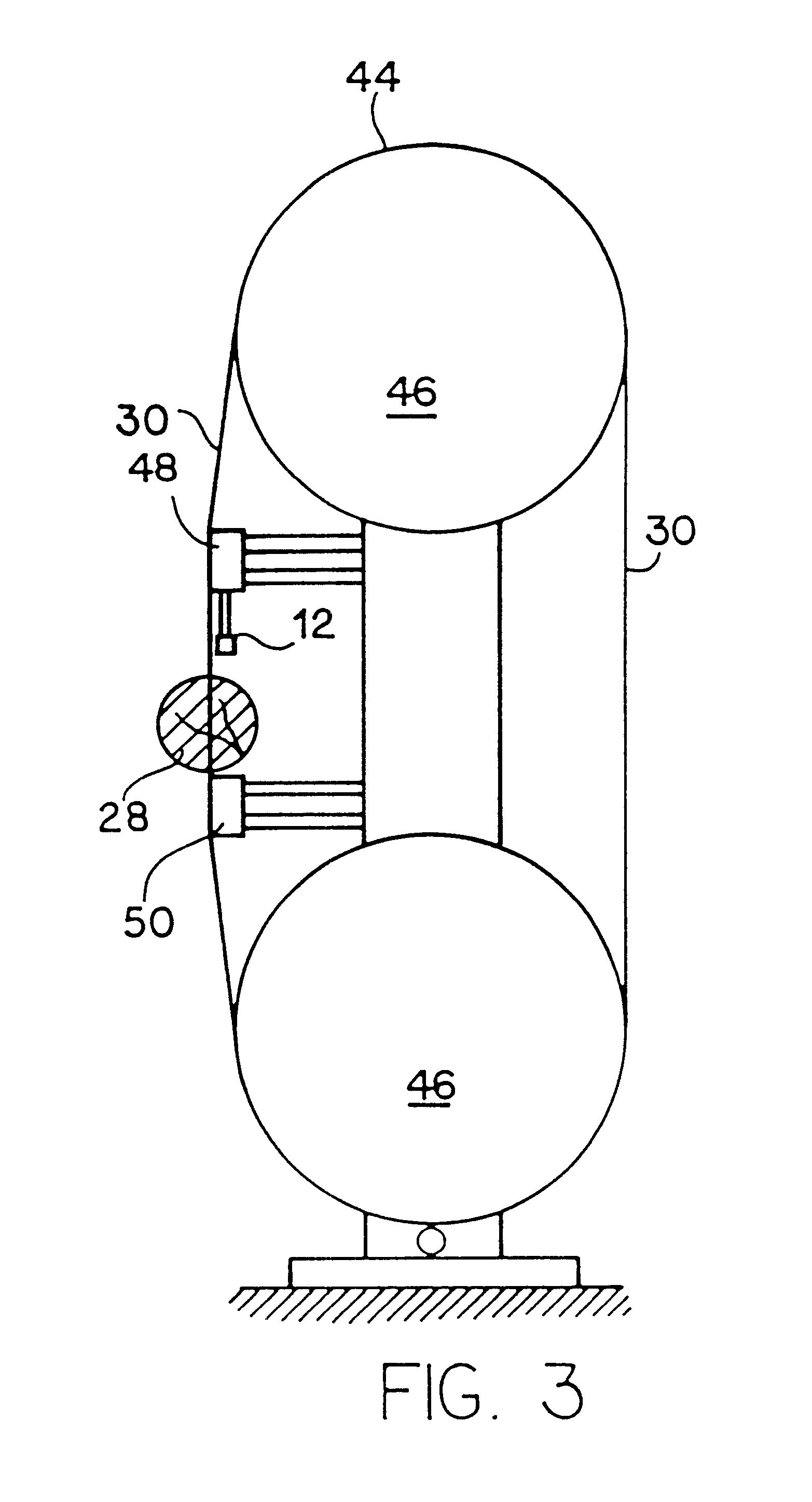
It is an object of the present invention to optimize production of cutting products. To do this, it is necessary to understand the sawblade cutting process and to adjust sawblade rim speed and / or feed speed to ensure that optimal straight light cuts are achieved at the fastest possible rate. Reference is made to prior art FIGS. 1 and 2. Prior art FIG. 1 discloses a section of a band saw cutting blade 30 which is formed of body 32 and teeth 34. The dynamics of band saw cutting will be described in this preferred embodiment in the context of a band saw cutting dimensional lumber from a log or cant. However, it should be understood that the dynamics of cutting with other materials are essentially the same, as are the dynamics of cutting with a radial saw, as opposed to a band saw. The processes in the control system described herein apply equally well to the cutting of other materials, including metal, polymers, rods, silicates, and virtually any material which is capable of being cut....


PUM

PropertyMeasurementUnit
widthsaaaaaaaaaa
timeaaaaaaaaaa
timeaaaaaaaaaa

Abstract

A positioned sensing device measures and / or calculates the lateral position and movement of a saw blade. These measured and calculated values are used to automatically alter the work-feed rate and / or saw blade rim speed either up or down as sawing conditions change within the work piece or between different work pieces.

Description

DESCRIPTION1. Technical FieldThis invention relates to circular saw and bandsaw machines, and incorporates a method of controlling the rate at which work is fed into the saw blade based upon performance of the saw blade within predetermined levels of stability.2. BackgroundCircular saw and bandsaw machines have long been used as economical means for cutting wood, metal and other materials. In recognition of the high costs for raw material and labor, automatic / computer control of work feed rates and sawing accuracy becomes of paramount importance. Optimized automatic control of work feed rates and saw blade stability keeps material and production costs down. The use of thinner saw blades and smaller rough sawn dimension sizes can conserve natural resources in the wood products industry, and reduce material waste in all industries which use circular saw and bandsaw machines in the manufacturing process. In the lumber industry, current production methods result in a larger than necessa...

Claims


Application Information

Patent Timeline
Patent Type & Authority Patents(United States)
IPC IPC(8): B23Q15/12B23D59/00B23Q15/007
CPCB23D59/002B23Q15/12G05B2219/49106G05B2219/45144G05B2219/37386Y10T83/04Y10T83/0605Y10T83/141Y10T83/148Y10T83/152Y10T83/159Y10T83/175Y10T83/7076Y10T83/7145
Inventor SMITH, H. REID
Owner SMITH H REID
Learn More