Liquid filter construction and methods

a technology of liquid filter and construction method, which is applied in the direction of filtration separation, separation process, manufacturing tools, etc., can solve the problems of filter head not being spun off from the filter head, system strength not optimized, and failure typically occurring at the rolled lock joint, so as to improve burst strength and impulse fatigue strength, the effect of eliminating the use of a roll or lock seam

Inactive Publication Date: 2002-05-07
DONALDSON CO INC +1
View PDF32 Cites 48 Cited by
  • Summary
  • Abstract
  • Description
  • Claims
  • Application Information

AI Technical Summary

Benefits of technology

Referring again to FIG. 3, in the arrangement shown, the seal member 92 is circular and circumscribes the flow ports 84. The seal member 92 is axially compressed against filter head 42 to form a seal between the filter head 42 and the filter cartridge 40. This seal helps to prevent leakage between the cartridge 40 and the filter head 42. In preferred constructions, the seal member 92 will be made from nitrile rubber.
In the embodiment of FIG. 9, a plurality of tacks or stitches between the can 56 and baffle plate 58 are initially applied. Preferably, the tacks are spaced apart from each other sufficient to hold the baffle plate 58 to the can 56 and prevent a gap from forming between the can 56 and baffle plate 58.

Problems solved by technology

If, under a burst test, the system fails at some point other than along a longitudinal seam, this means that, theoretically, the system has not been optimized for strength.
In previous existing filters having a rolled lock joint connection between the gasket retainer and the housing, as pressure is increased to the point of mechanical failure, the failure typically occurs at the rolled lock joint.
In addition, in previous existing filters having a rolled lock joint connection between the gasket retainer and the housing, there are other problems as well.
When the projection welds break, the filter cannot be spun off from the filter head.

Method used


Image

  • Liquid filter construction and methods
  • Liquid filter construction and methods
  • Liquid filter construction and methods

Examples


Embodiment Construction

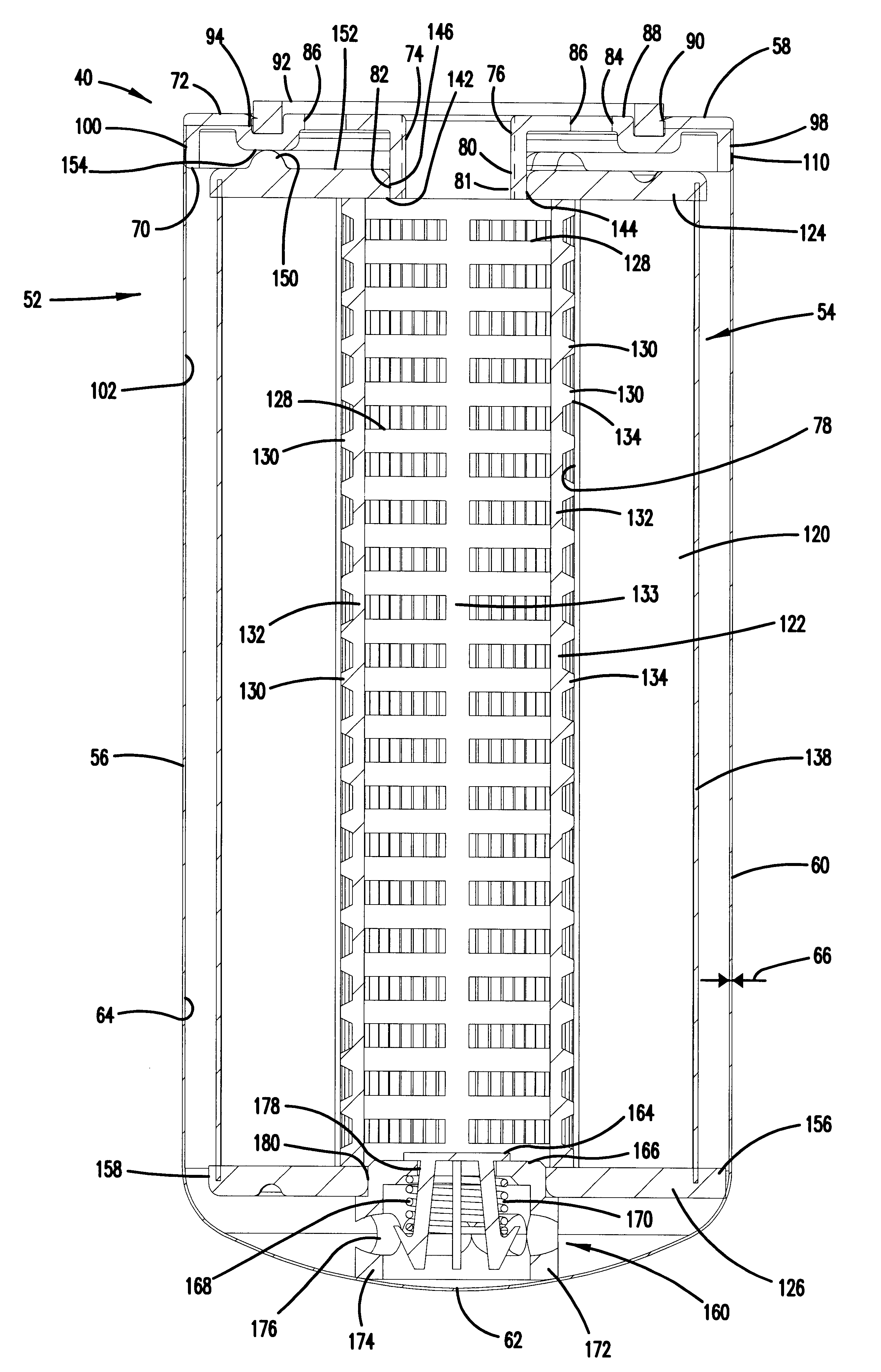
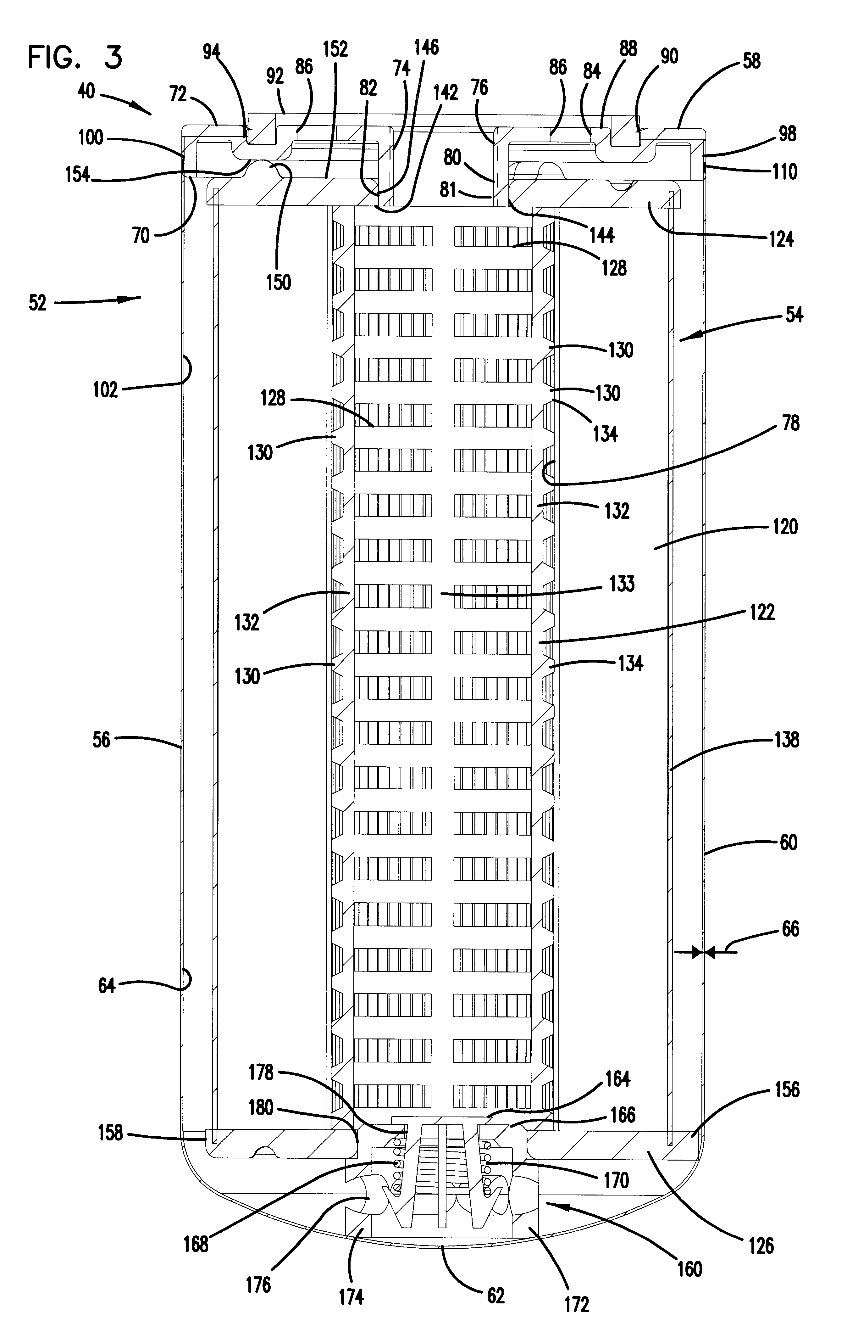
The following section provides example dimensions of one specific embodiment. It should be understood that a variety of dimensions and configurations are contemplated.

The can 56 will have a length of at least a 100 mm, no greater than 500 mm, typically 150-300 mm, and in one example about 200 mm. The diameter of the can 56 will typically be at least 40 mm, no greater than about 150 mm, typically about 50-100 mm, and in one example about 90-95 mm.

The seal member 92 will have a diameter that is 5-25% smaller than the diameter of the can 56. Typically, the diameter of the seal member 92 will be on the order of 8-15% smaller than the diameter of the can 56. The diameter of the seal member 92 will typically be at least 30 mm, no greater than about 140 mm, typically about 50-100 mm, and in one example about 80-85 mm.

The filter element 54 will have a length between the first and second end caps 124, 126 that is typically at least 70%, no greater than 95%, and typically about 80-90% of the ...


PUM

PropertyMeasurementUnit
thicknessaaaaaaaaaa
thicknessaaaaaaaaaa
thicknessaaaaaaaaaa

Abstract

Liquid filter constructions include a baffle plate secured to a can, by way of laser welding. A filter element is operably oriented within the interior of the can. The filter element includes a first end cap and a media pack secured to the first end cap. In some embodiments, the first end cap radially abuts an outer, annular surface of a tubular member of the baffle plate to form a radially directed seal between the first end cap and the tubular member. Liquid filter constructions of this type have a burst strength between 500-800 psi (about 3.4-5.5 MPa), along a longitudinal section of the can wall. Constructions of this type eliminate a roll or lock seam, an inner gasket, an inner compressive spring, and a gasket retainer. Systems for using liquid filters are described herein. Methods of constructing and using these types of filter arrangements are also described.

Description

This disclosure relates to fluid filters including their construction and use. In particular, this disclosure concerns liquid filters to clean contaminants from fluid systems such as engine and transmission lubrication systems, engine fuel systems, and hydraulic systems.Certain types of fluid filters, for example oil or lube filters, fuel filters, or hydraulic fluid filters, operate to remove substantial amounts of particulate material from liquid flow, typically in a circulating environment.Such filters generally include a filter element within a drawn, relatively thin, cylindrical metal housing and a stamped metal baffle or cover plate at the open end of the housing. Typically, there is a gasket retainer projection welded to the cover plate, and the gasket retainer is secured to the housing by a roll or lock seam. A central threaded opening is provided in the cover plate for spinning the filter onto a threaded stud of a mounting base or filter head.Fluid filters of this type can b...

Claims


Application Information

Patent Timeline
Patent Type & Authority Patents(United States)
IPC IPC(8): B01D27/00
CPCB01D27/005B01D27/08B01D27/103B01D2201/291B01D2201/302B01D2201/304B01D2201/4046
Inventor STENERSEN, EIVINDHARDER, DAVID B.HACKER, JOHN R.KIRAL, GERALD D.STREITMATTER, RONALD W.SOCHA, KEVIN K.
Owner DONALDSON CO INC
Why Eureka
Try Eureka