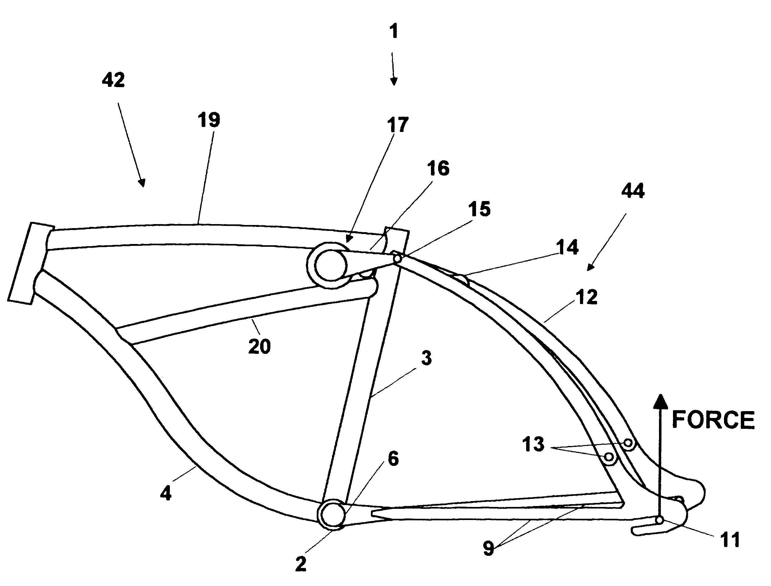
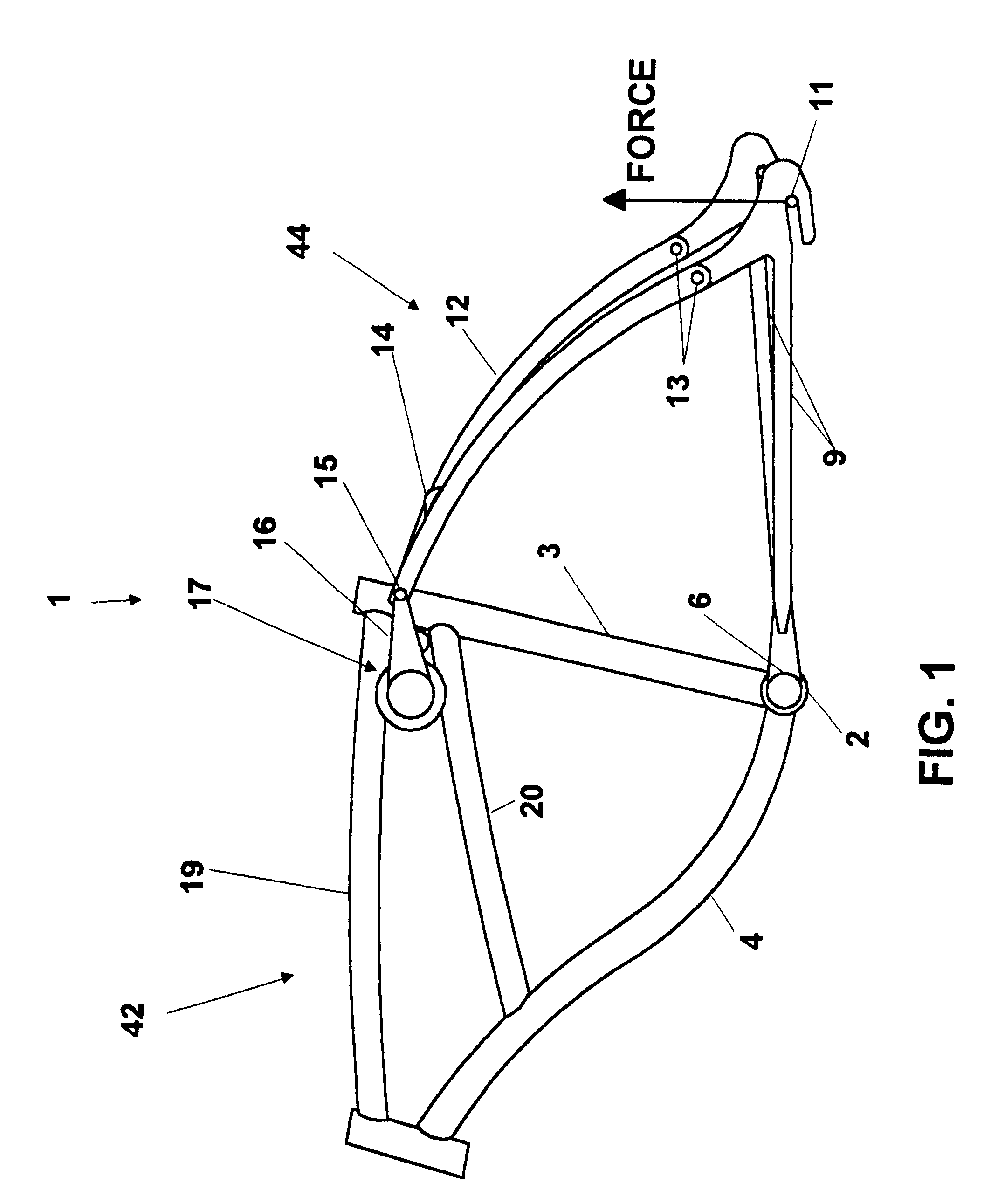
Bicycle with shock absorber
- Summary
- Abstract
- Description
- Claims
- Application Information
AI Technical Summary
Problems solved by technology
Method used
Image

Examples
second preferred embodiment
Rubber Torsion Shock Absorber--with Hysteresis Damping
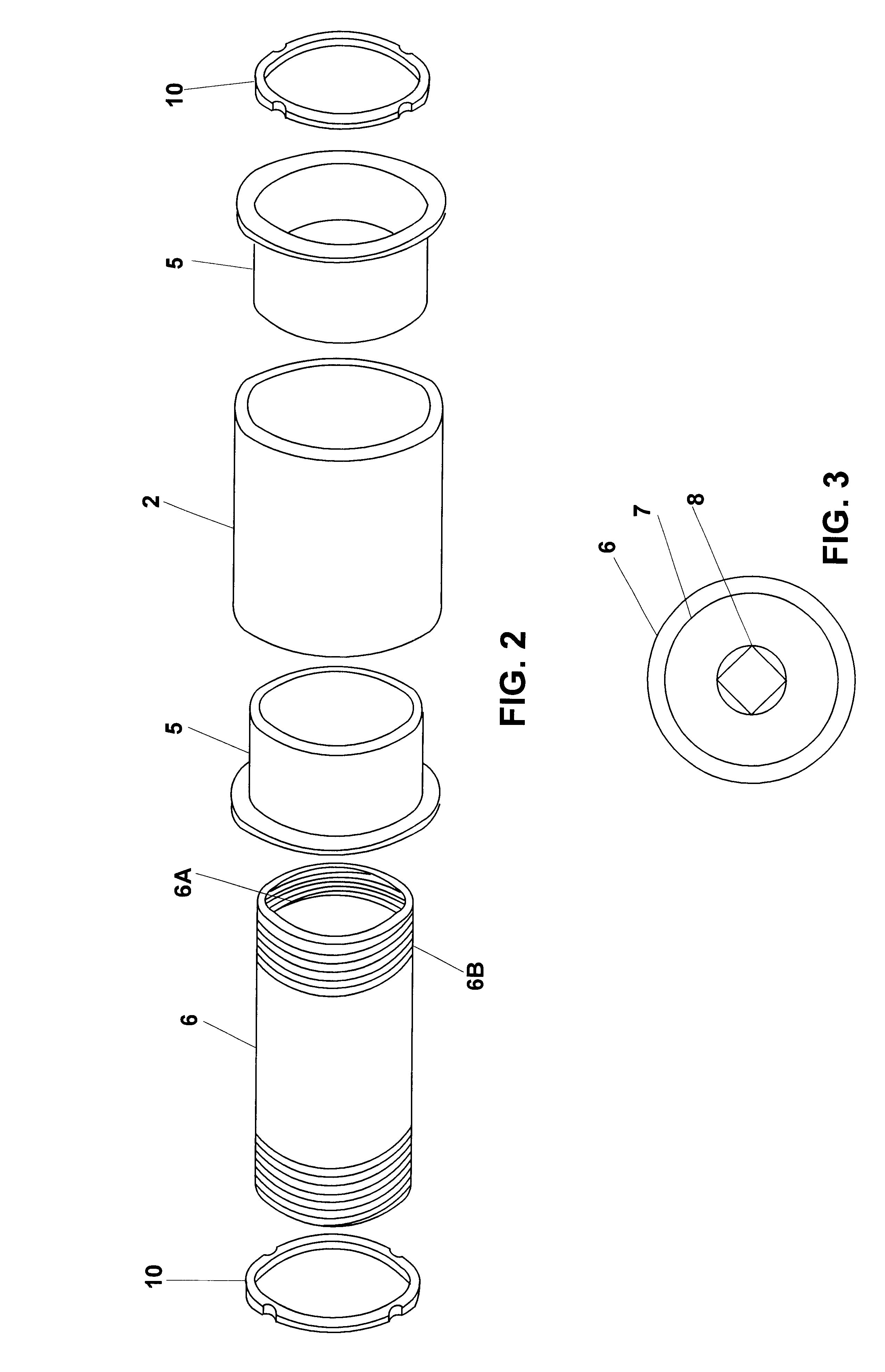
A second preferred embodiment utilizes hysteresis damping to dampen the motion of torsion spring 50. Hysteresis damping as applied to a spring is where spring energy is dissipated through the deformation of a resilient, substantially solid state damping material. In a preferred embodiment of the present invention, the substantially solid state material is rubber.
A second embodiment of torsion spring assembly 17 is made by substituting the elements described in FIG. 6E (i.e., plastic friction washers 25) with elements described in FIGS. 8A and 8B. Instead of placing plastic friction washers 25 between torsion arms 16 and outer housing 18B, components are inserted to add a damping effect to the torsional motion resisted by torsion spring 50. As seen in FIG. 8B, outer housing 18B has key cutout 18C. Elastomer plate 26 is made out of a high loss factor rubbery substance. Metal elastomer backing plate 26A is cut to fit at key cutout 1...
second embodiment
Installing Second Embodiment
All procedures of installing the second embodiment are identical to that of the first embodiment through the installation of actuation shafts 23. Elastomer plates 26 are bonded to elastomer backing plates 26A, which are then keyed to key cutout 18C of outer housing 18B. Rolling indentors 28 are then placed against rolling indentor retainers 27 and both are slid over actuation shafts 23 and pressed against elastomer plates 26. Torsion arms 16 are then slid over shafts 23 and the entire assembly is tightened with bolt 24 and nut 24A as described above under the first embodiment.
Operation of the Damper
As torsion arms 16 cause actuation shafts 23 to rotate, indentor retainers 27 rotate as well. However, elastomer plates 26 remain essentially stationary because they are keyed to key cutout 18C of outer housing 18B. Between rotating elastomer plates 26 and indentor retainers 27 are rolling indentors 28. As indentor retainers 27 rotate around shafts 23, rolling ...
third preferred embodiment
Adjustable Preload and Damping
A third preferred embodiment showing adjustable preload capability is seen by reference to FIGS. 12 and 13. FIG. 12 shows an exploded view of torsion spring assembly 17 with adjustable preload. In FIG. 12 only the right side components are shown. It should be noted that the left side components are identical to right side except that there is just one torsion spring 50 and just one threaded rod 400. In this embodiment, bracket 100 is welded to top tube 19. Torsion spring 50 is press fit inside spring housing 110. Preload cable assembly 112 is then attached to spring housing 110 so that cable stop 114 is adjacent to key 116 of spring housing 110. Spring housing 110 and preload cable assembly 112 are lowered into the pocket in lower shell 104. Lower shell 104 allows for free rotation of spring housing 110 and preload cable assembly 112, but no axial motion. Upper shell 102 is then snapped to lower shell 104 and lower shell 104 is mounted to bracket 100 wi...
PUM
 Abstract
Description
Claims
Application Information