Hand held grinder

Inactive Publication Date: 2002-05-14
CURETON THOMAS D
View PDF20 Cites 44 Cited by
  • Summary
  • Abstract
  • Description
  • Claims
  • Application Information

AI Technical Summary

Benefits of technology

The grinder may also include a drive shaft coupled to the motor, a driving gear coupled to the drive shaft, and a driven gear engaging the driving gear and fixed to the mounting surface. The driven gear and the mounting surface may be part of a unitary member. Such a unitary construction allows the grinder to be more compact.
The housing may define a bottom housing surface that is substantially coplanar with the mounting surface. This substantially coplanar construction allows the grinder to be constructed so that only a very small gap separates the grinding wheel from the housing, thereby producing a more compact grinder. The housing may also define a top housing surface opposite from the bottom housing surface and an angled housing surface

Problems solved by technology

However, past hand held grinders have not been able to reach many surfaces

Method used


Image

  • Hand held grinder
  • Hand held grinder
  • Hand held grinder

Examples


Embodiment Construction

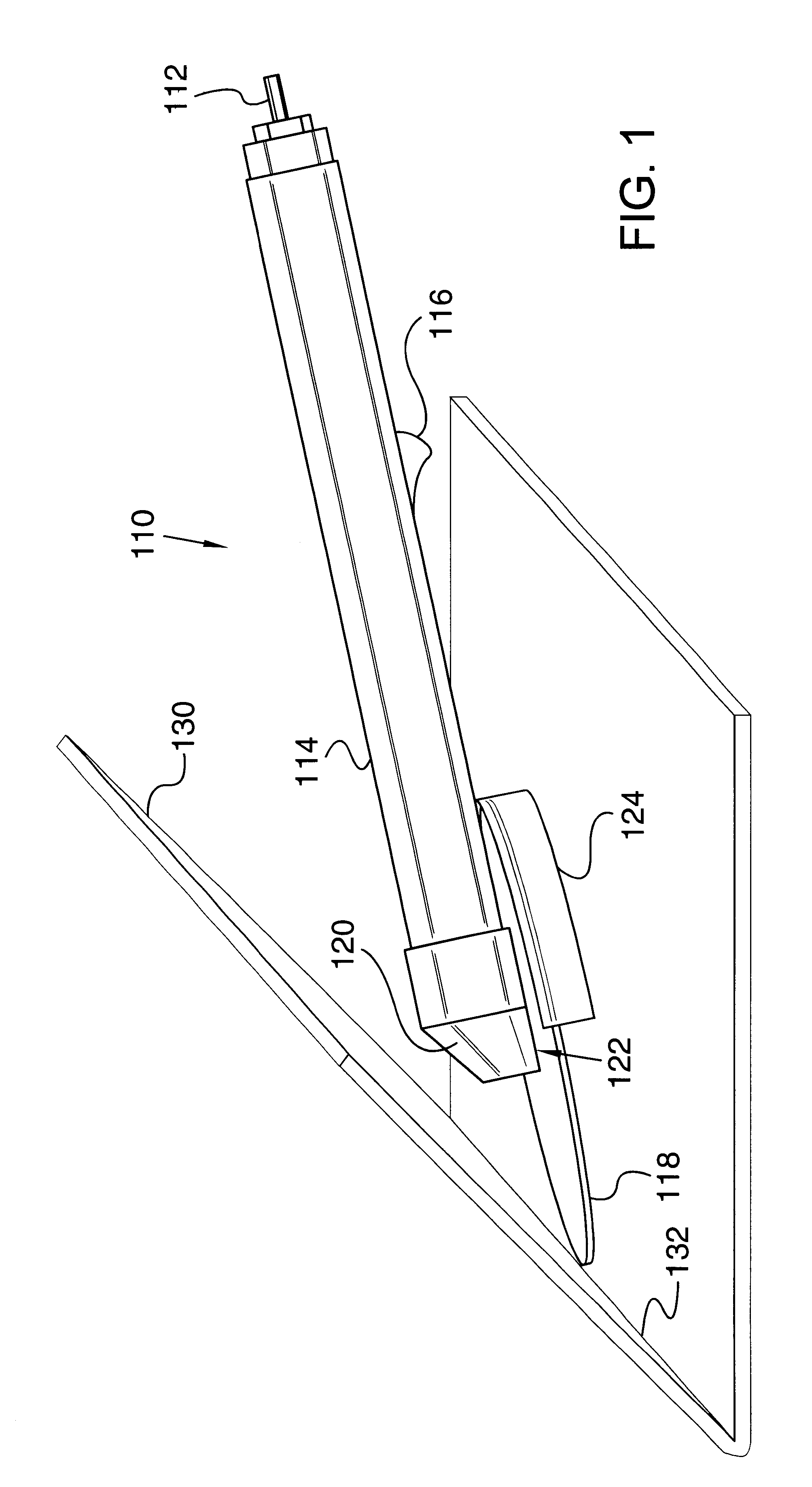
Referring to FIG. 1, a grinder 110 includes a power input 112 that is housed within a housing 114. In the embodiment shown, the grinder is a pneumatic grinder and the power input is a fitting for attaching grinder 110 to an air hose that supplies pressurized air to grinder 110. However, the present invention is also well-suited to grinders that are powered by other power sources, such as electric power sources. Power input 112 communicates pressurized air to a motor (not shown) that is also housed within housing 114. A trigger mechanism 116 preferably activates the motor when it is depressed by a user and deactivates the motor when it is not depressed. The motor is preferably mechanically coupled to a grinding wheel 118 that extends beyond an end 120 of housing 114. End 120 is preferably tapered, and grinding wheel 118 is preferably parallel with and very close to a bottom surface 122 of housing 114. A shield 124 is attached to grinder 110 and protects a user from contact with wheel...


PUM


Abstract

A hand-held grinder includes a motor and a mounting surface coupled to the motor. A housing supports the mounting surface and the motor. A grinding wheel abuts and is secured to the mounting surface, and the grinding wheel extends beyond an end of the housing. A line that is tangential with the grinding wheel distal from the housing, and that is tangential with the end of the housing, may be at an angle of less than about 45° relative to a plane of rotation of the grinding wheel. The grinder may also include a drive shaft coupled to the motor, a driving gear coupled to the drive shaft, and a driven gear engaging the driving gear and fixed to the mounting surface. The driven gear and the mounting surface may be part of a unitary member. The housing may define a bottom housing surface that is substantially coplanar with the mounting surface. The housing may also define a tapered end. The grinder may also include a telescoping feature wherein the housing includes a first member that is moveable relative to a second member to change a length of the grinder. The grinder may include a lock pin that may be selectively forced into engagement with the drive shaft, thereby preventing rotation of the drive shaft relative to the housing.

Description

1. Technical FieldThis invention generally relates to a grinder, and more specifically relates to a compact grinder.2. Background ArtHand held grinders are common tools that are used for a variety of applications. Typically a grinder includes a motor that drives a wheel (such as a grinding wheel, wire brush, or cutting disc). Many grinders include a drive shaft from the motor and a gear system coupled to the drive shaft that changes the direction of rotation. Often the direction of rotation is changed by 90.degree.. Also, many grinders include a lock pin that can be pressed inwardly to lock the drive shaft relative to the housing of the grinder so that a clamping screw can be loosened or tightened to mount the wheel on the grinder or remove the wheel from the grinder.Hand held grinders are useful because they are portable and thus the grinders can be taken to the part to be worked, rather than the part having to be moved to a stationary grinder. They are often useful in working surf...

Claims


Application Information

Patent Timeline
IPC IPC(8): B24B23/02B24B23/00B24B45/00
CPCB24B45/006B24B23/02
Inventor CURETON, THOMAS D.
Owner CURETON THOMAS D
Why Eureka
Try Eureka