Forklift having a light source and lens combination that provide a shaped light beam

a technology of light source and lens combination, applied in the field of forklifts, can solve the problem of not losing sight of the impinging position, and achieve the effect of convenient use and smooth loading and unloading

Inactive Publication Date: 2002-05-14
NIPPON YUSOKI
View PDF10 Cites 31 Cited by
  • Summary
  • Abstract
  • Description
  • Claims
  • Application Information

AI Technical Summary

Benefits of technology

Because the shape of the illuminated cross of the laser light has a certain degree of length in the horizontal direction and the vertical direction, if the center of the cross has a little gap from the pallet, the user can easily adjust the center of the cross to the desirable position without missing the illuminated position of the laser light.
As mentioned above, the lens 50 may be configured so as to be detachable from the cylinder 10, so that the light spot of the laser light can be changed so as to be formed into a spot-like shape or a line shape according to each of situations, thereby enabling the device to be used more conveniently.
According to the invention, as described above, the light beam emitted from the laser light source is formed into a lateral shape which elongates in the width direction of a pallet. The light spot 20 is surely formed in a gap between a load and another load 9, the insertion openings of the pallet 17, and the like. Namely, the light spot 20 which laterally elongates is always formed. As a result, the invention attains an effect that the operator is prevented from losing sight of the light spot 20 and hence loading and unloading works can be smoothly conducted.

Problems solved by technology

As a result, there arises a problem in that sight of the impinging position is not lost.

Method used


Image

  • Forklift having a light source and lens combination that provide a shaped light beam
  • Forklift having a light source and lens combination that provide a shaped light beam
  • Forklift having a light source and lens combination that provide a shaped light beam

Examples


Embodiment Construction

(Function)

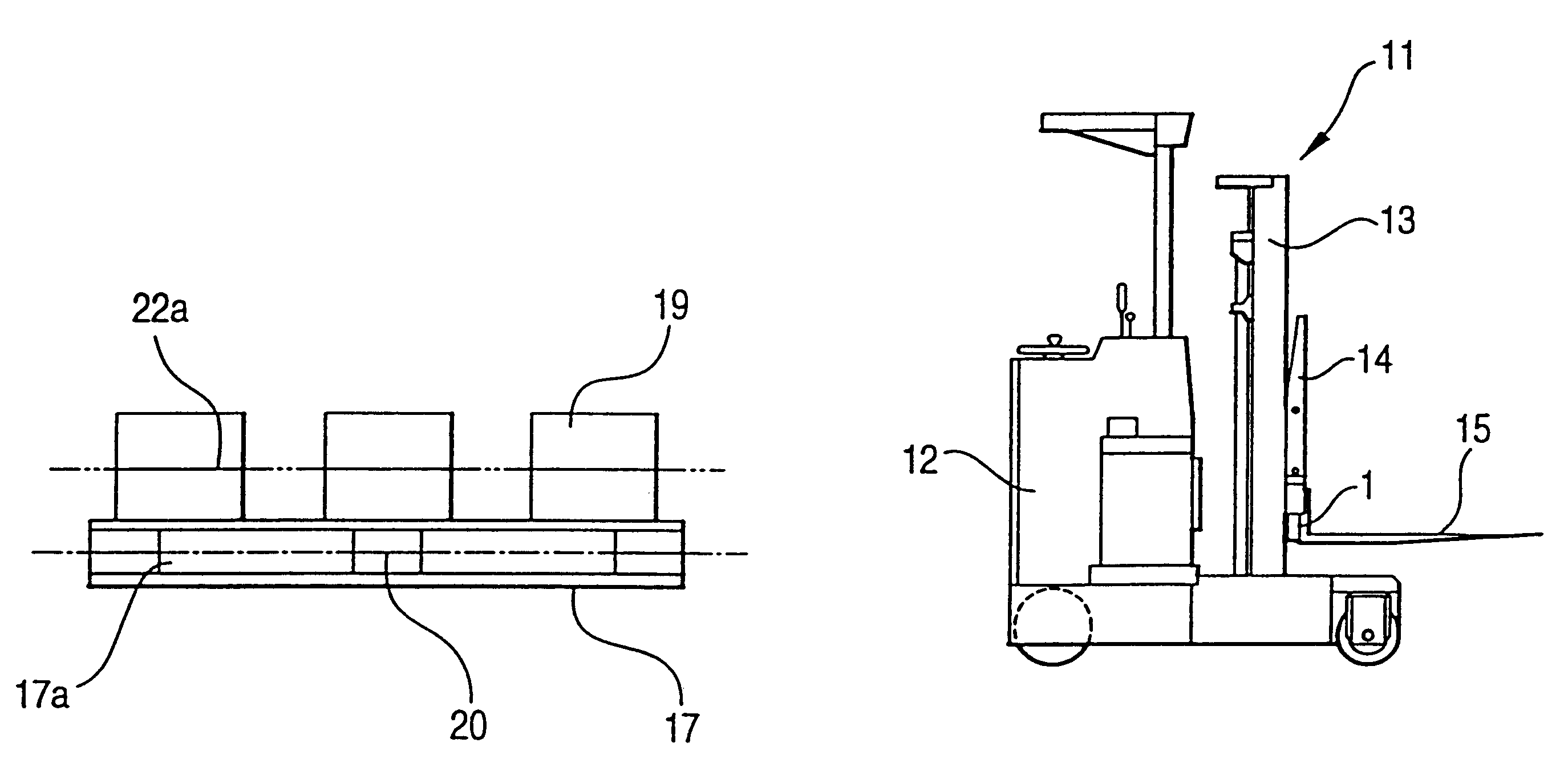
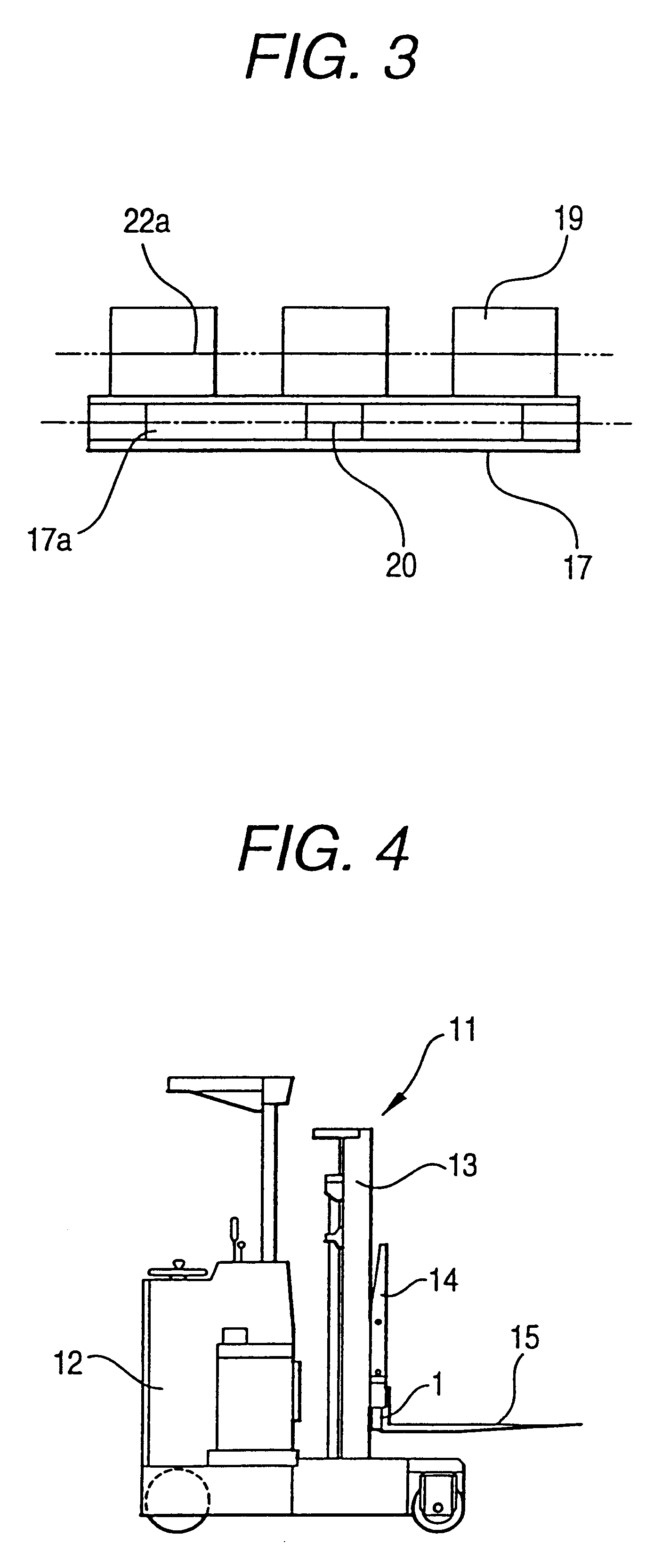
When a light beam is emitted toward a pallet from a laser light source which is attached to a lift bracket or a fork so as to illuminate tines of the fork, the light beam which is expanded by the lens into a fan-like shape in a plan view impinges on the pallet. As a result, as shown in FIG. 3, a linear light spot 20 is formed which extends over right and left ends and a center beam portion that cooperate to form fork insertion openings 17a between a deckboard and an edgeboard.

Description of the Present Invention

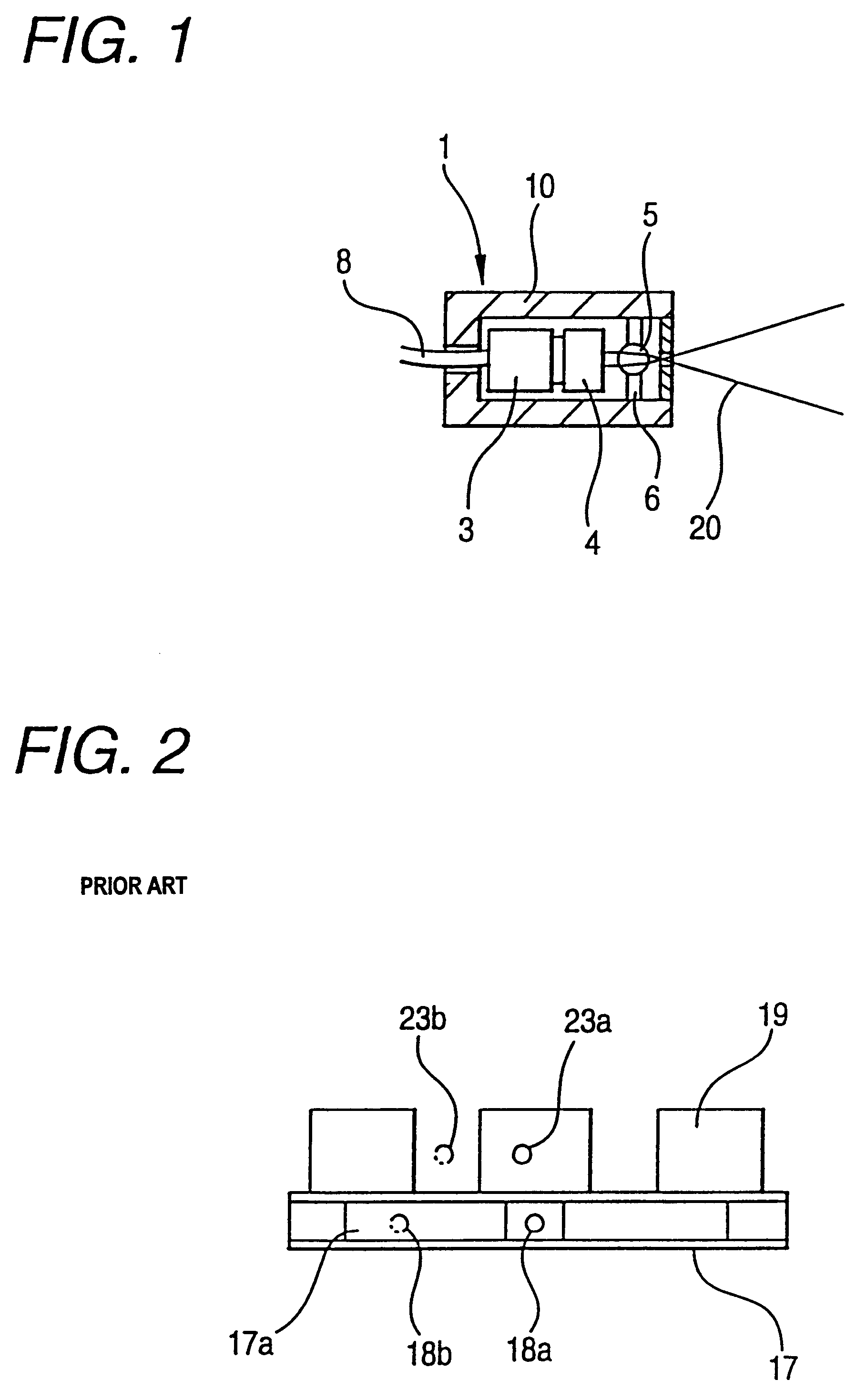
The description will be described in detail with reference to the accompanying drawings. Firstly, an optical pallet detecting device will be described with reference to FIG. 1. An optical pallet detecting device 1 comprises a connector 3 which is connected to an electric energy source via an electric wire 8, a laser light source 4, a lens 5, and a lens fixing member 6. These components are fixed to the inside of a hollow cylinder 10.

The lens 5 has a cylindrical shap...


PUM


Abstract

There is provided a forklift in which a mast upstands in front of the body of the forklift, a lift bracket is mounted on the mast in a vertically movable manner, and a fork is engaged with the lift bracket, wherein a laser light source which illuminates an area in front of the fork is attached to the lift bracket or the fork, and a light beam emitted from the laser light source is formed into a shape which laterally elongates, via a lens.

Description

1. Field of the InventionThe present invention relates to a forklift in which when a load is to be loaded on a pallet or a rack, the pallet or the like is illuminated with a laser beam so that its position is visually recognized.2. Description of the Related ArtIn a conventional forklift using a laser light source, as shown in FIG. 2, a light spot projected onto a pallet 17 has a spot-like shape.As described above, in an optical pallet detecting device using a laser light source, conventionally, a light spot projected onto the pallet 17 has a spot-like shape. As shown in FIG. 2, when the light beam impinges on an insertion hole 17a of the pallet 17, therefore, a light spot 18a is not formed as indicated by a chain line 18b. When the light beam impinges on a gap between adjacent loads 19, a light spot 23a is not formed as indicated by a chain line 23b. As a result, there arises a problem in that sight of the impinging position is not lost.According to the invention, the problem is so...

Claims


Application Information

Patent Timeline
Patent Type & Authority Patents(United States)
IPC IPC(8): B66F9/075B66F9/07B66F9/24
CPCB66F9/0755
Inventor KOKURA, KAZUMASA
Owner NIPPON YUSOKI
Why Eureka
Try Eureka