Disk drive including resilient securing system providing relative movement between side rails and head disk assembly to accommodate side rails engaging guide channels in a chassis

a resilient securing and disk drive technology, applied in the field can solve the problems of increasing the guide channels of the chassis may not be properly aligned, and the cost of providing these components can further increase the cost of hard disk drives

Inactive Publication Date: 2002-05-14
WESTERN DIGITAL TECH INC
View PDF9 Cites 108 Cited by
  • Summary
  • Abstract
  • Description
  • Claims
  • Application Information

AI Technical Summary

Problems solved by technology

As such, the process of mounting the side rails to the side walls of the head disk assembly can be a time consuming process that results in higher costs for assembling the hard disk drive.
Moreover, since the side rail mounting process entails the use of two side rails and at least four threaded fasteners, the cost of providing these components can further increase the cost of the hard disk drive.
While the jig assembly helps to ensure that the side rails are properly aligned (i.e., parallel) with one another, the guide channels of the chassis may not be properly aligned.
Unaligned (i.e., non-parallel) guide channels within the chassis may make it difficult to align and insert the side rails of the head disk assembly with and into the guide channels of the chassis.
Moreover, since the threaded fasteners secure the side rails to the side walls of the head disk assembly in a fixed position, the side rails can only accommodate (i.e., tolerate) a minute amount of guide channel misalignment.
As such, unaligned guide channels can result in a hard disk drive that is virtually impossible to mount within the chassis without some modification of the alignment of the side rails, the guide channels or both.
Even if the unaligned guide channels can accept the side rails so that the hard disk drive can be mounted in the chassis, this misalignment can result in unwanted stresses on the side rails and guide channels that may result in hard disk drive affecting failure of one or more of these components.
However, in order to reduce manufacturing costs, the side rails and the guide rails are not manufactured to a high degree of precision.
This "play", whether side-to-side or up-down, that exits between the side rails and the guide channels can degrade performance of the hard disk drive.
Performance of the hard disk drive can be affected by vibration, caused by operation of other components within the chassis, of the hard disk drive that is a result of the play between the side rails and the guide rails.
This vibration can be caused by undesirable imbalance in the disk stack and during actuator seeking.
Vibration of the hard disk drive can affect performance of the hard disk drive itself and can produce undesirable acoustic noise (i.e., buzzing sound).
Moreover, operation of the hard disk drive itself together with the "play" between the side rails and the guide rails can produce mechanical energy that can cause operation and performance affecting vibration in other components such as other disk drives within the chassis.
In particular, there is a need for a side rail mounting system that employs less components and reduces the time for mounting the side rails to the head disk assembly, thereby resulting in assembly time and cost savings.

Method used


Image

  • Disk drive including resilient securing system providing relative movement between side rails and head disk assembly to accommodate side rails engaging guide channels in a chassis
  • Disk drive including resilient securing system providing relative movement between side rails and head disk assembly to accommodate side rails engaging guide channels in a chassis
  • Disk drive including resilient securing system providing relative movement between side rails and head disk assembly to accommodate side rails engaging guide channels in a chassis

Examples


Embodiment Construction

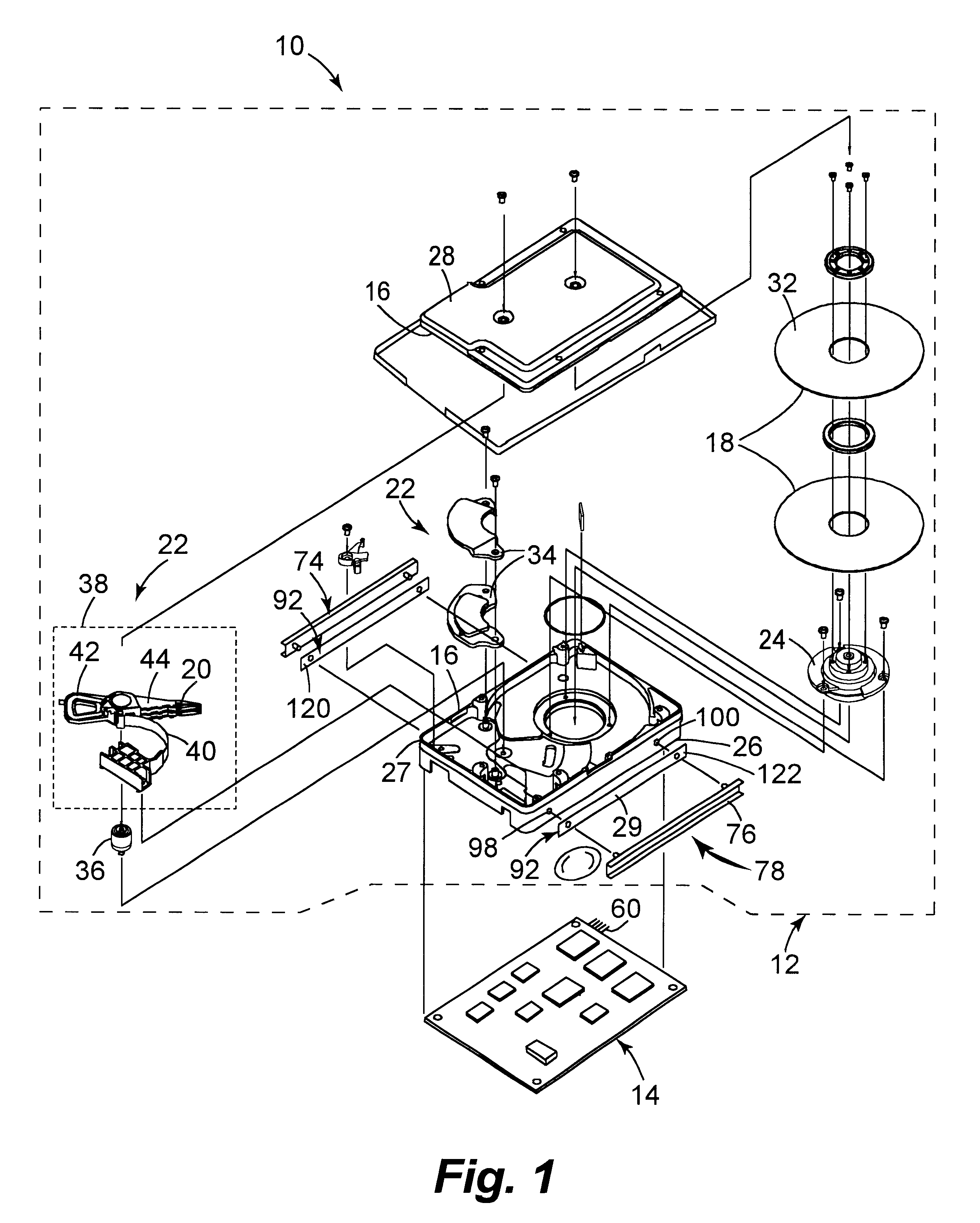
As shown in FIG. 1, a hard disk drive 10 embodying one preferred embodiment of the present invention includes a head disk assembly 12 and a printed circuit board assembly 14. The printed circuit board assembly 14 is suitably secured to an exterior of the head disk assembly 12 and controls operation of various components thereof.

The head disk assembly 12 includes an enclosure 16, a magnetic disk 18, a magnetic transducer 20, a rotary actuator arrangement 22,and a spindle motor generally indicated at 24. As described in greater detail below, the magnetic disk 18, the magnetic transducer 20, the rotary actuator arrangement 22 and the spindle motor 24 are maintained within the enclosure 16.

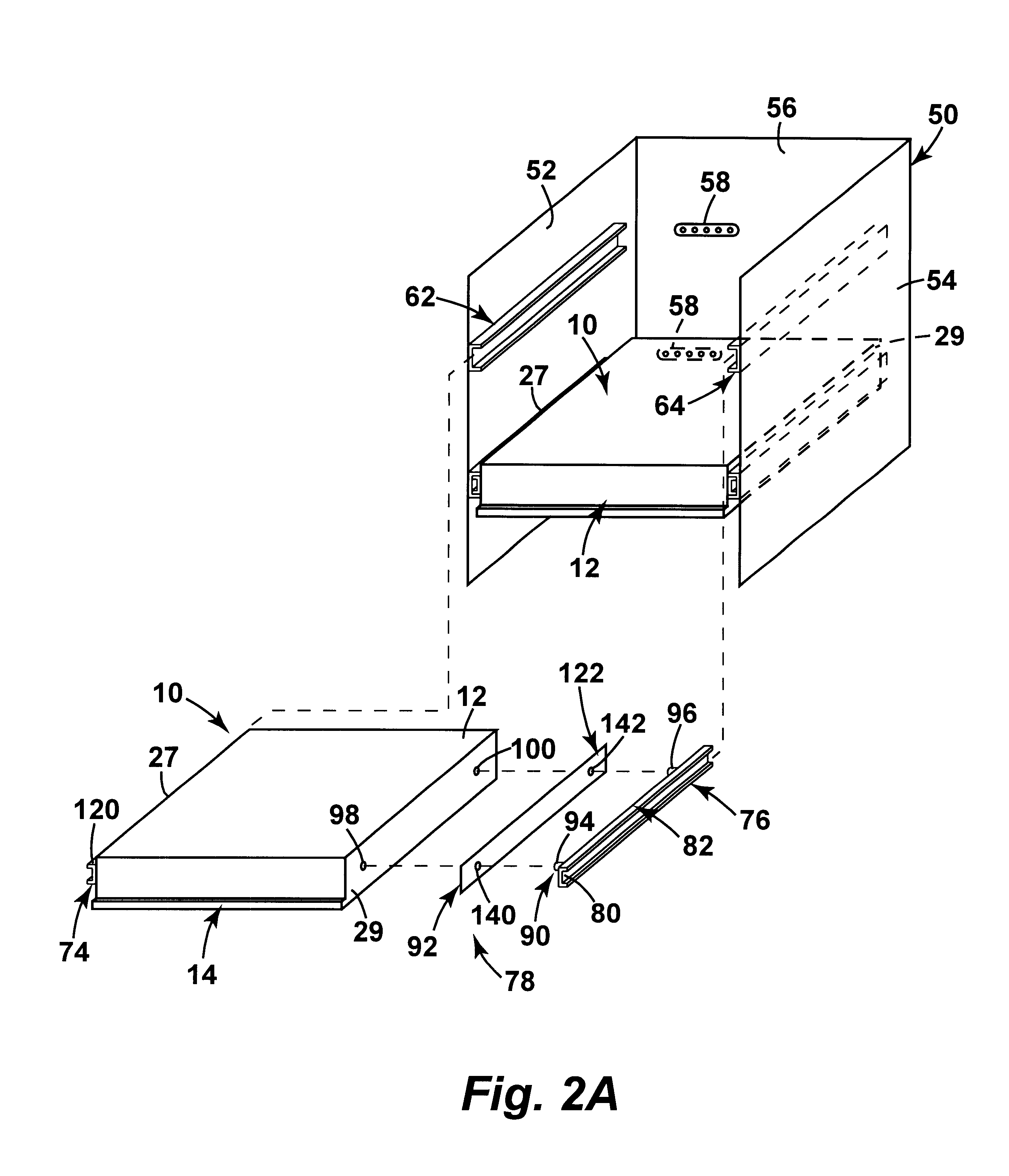
The enclosure 16 comprises a base 26 and a cover 28. The base 26 defines first and second side walls 27 and 29, respectively, of the head disk assembly 12 of the hard disk drive 10. The enclosure 16 is sealed to provide a relatively contaminant-free interior for remaining components of the head disk a...


PUM

PropertyMeasurementUnit
movementaaaaaaaaaa
pressure sensitiveaaaaaaaaaa
resilientaaaaaaaaaa

Abstract

A disk drive is usable in a chassis having first and second guide channels mounted on side surfaces of the chassis. The disk drive includes a head disk assembly that includes first and second side walls. The disk drive further includes first and second side rails and a securing system for securing the side rails to the side walls. The first and second side rails engage the first and second guide channels, respectively, for supporting the disk drive within the chassis. The securing system includes an engagement mechanism and a double-sided adhesive resilient mechanism. The engagement mechanism projects between the first and second side rails and the first and second side walls, respectively, of the head disk assembly. The double-sided adhesive resilient mechanism is adhesively attached between the first side rail and the first side wall and between the second side rail and the second side wall for mounting the first and second side rails to the first and second side walls, respectively, of the head disk assembly. The securing system provides for relative movement between the side rails and the side walls to accommodate the side rails engaging the guide channels in the chassis. In one embodiment, the relative movement is a damped relative movement.

Description

1. Field of the InventionThe present invention relates to hard disk drives. More particularly, this invention relates to a disk drive including a resilient securing system providing relative movement between side rails and head disk assembly to accommodate side rails engaging guide channels in a chassis.2. Description of the Prior Art and Related InformationA huge market exists for mass-market host computer systems such as servers, desktop computers, and laptop computers. To be competitive in this market, a hard disk drive must be relatively inexpensive and must accordingly embody a design that is adapted for low cost mass production. In addition, it must provide substantial capacity, rapid access to data, and reliable performance. Numerous manufacturers compete in this expansive market and collectively conduct substantial research and development, at great annual cost, to design and develop innovative hard disk drives to meet increasingly demanding customer requirements.Each of the...

Claims


Application Information

Patent Timeline
Patent Type & Authority Patents(United States)
IPC IPC(8): G11B33/12
CPCG11B33/128G11B33/121
Inventor BROOKS, PETER E.GABRIELSON, LANCE A.
Owner WESTERN DIGITAL TECH INC
Why Eureka
Try Eureka